Filtreringsvillkor
  • Material
    • Stainless Steel
  • Surface Treatment
  • Material Details
  • D Tolerance
  • Shaft Dia. D(mm)
  • Length L(mm)
      [15-1000/0.1mm units]
    • A(mm)
        [2-150/0.1mm units]
      • Keyway (1) [KA](mm)
          [0-1000/0.1mm units]
        • Type
          • CAD
          • Uppskattade leveransdagar
            • Alla
            • Inom 4 arbetsdagar
            • Inom 6 arbetsdagar

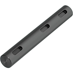
          Rotary Axes / Keyway / Optional Machining

          Artikelnummer:

          Ej färdigt: 16 kandidater hittades.
          Antal:

          Skiss och specifikationstabell

          Dimensional Drawing

          Rotary Shaft - Straight with Keyway   Dimensional Drawing
          ■Detailed Keyway Dimensions
          Rotary Shaft - Straight with Keyway   Dimensional Drawing
          Shaft Dia.btr
          Reference DimensionTolerance
          (N9)
          Reference DimensionTolerance
          6 2- 0.004
          - 0.029
          1.2+ 0.1
           0
          0.08 or more
          0.16
          8·10 31.8
          12 4 0
          - 0.03
          2.5
          13 to 17 53.00.16 or more
          0.25
          18 to 22 63.5
          25·30 8 0
          - 0.036
          4.0+ 0.2
           0
          35105.00.25 or more
          0.4
          4012 0
          - 0.043
          5.0
          50145.5
          [ ! ] When KA < 1, KA + A = L, KB + B = L and L - KC - C < 1,
          keyway is shaped as shown below.
          Rotary Shaft - Straight with Keyway
          [ ! ] Surface roughness of Part D for h9 (Cold-drawn) is {{{attr2}}}. Surface roughness for h7 (Ground) and g6 (Ground) is {{{attr3}}}.
          [ ! ] Number of keyways can be specified up to 3.
          [ ! ] When multiple keyways are added, keep 2 mm or more clearance between them.
          [ ! ] High hardness stainless steel may have a center hole.
          Rotary Shaft - Straight with Keyway   Dimensional Drawing
          ■Circularity and Straightness
          [ ! ] Circularity and straightness of Part D are not applicable to h9 (Cold-drawn).
          ■Circularity of Part D
          DCircularity
          M
          overor Less
          5130.004
          13200.005
          20400.006
          40500.007
          ■Tolerances of L and Other Dimensions
          DimensionDimension
          Tolerance
          overor Less
          26±0.1
          630±0.2
          30120±0.3
          120400±0.5
          4001000±0.8
          TypeD Tolerance[M] Material[S] Surface Treatment
          (1)NSFMKRh9 (Cold-drawn)EN 1.1191 Equiv.
          SFMKRBlack Oxide
          PSFMKRElectroless Nickel Plating
          SSFMKREN 1.4301 Equiv.
          (2)NSFHKRh7 (Ground)EN 1.1191 Equiv.
          SFHKRBlack Oxide
          PSFHKRElectroless Nickel Plating
          SSFHKREN 1.4301 Equiv.
          (3)NSFGKRg6 (Ground)EN 1.1191 Equiv.
          SFGKRBlack Oxide
          PSFGKRElectroless Nickel Plating
          SSFGKREN 1.4301 Equiv.
          AHFGKRHigh Hardness Stainless Steel
          Hardness: 35HRC or More
          [!] High hardness stainless steel has a lower center hardness.

          Specification Table

           Part NumberL Keyway (1) Keyway (2) Keyway (3)
                   
           KAA KBB KCC
          1 Keyway
          2 Keyways
          3 Keyways
          SFMKR10
          SFHKR30
          SFGKR25


          325
          330
          350


          KA20
          KA20
          KA10


          A50
          A50
          A10


          KB120
          KB90


          B20
          B30


          KC210


          C30
          (1) h9 (Cold-drawn)
          Part NumberL
          0.1 mm Increments
          Keyway (1)Keyway (2)Keyway (3)
          TypeDh9KA·AKB·BKC·C
           Tolerance0.1 mm Increments
          NSFMKR

          SFMKR

          PSFMKR

          SSFMKR

          (D13, 17, 18 or 22 is not available for SSFMKR.)
          60
          −0.030
          15.0 to 500.0KA+A ≤ L

          KA ≥ 0

          b ≤ A ≤ 100
          KB+B ≤ L

          KB ≥ 0

          b ≤ B ≤ 100
          KC+C ≤ L

          KC ≥ 0

          b ≤ C ≤ 100
          80
          −0.036
          15.0 to 500.0
          1015.0 to 800.0
          120
          −0.043
          15.0 to 900.0
          1315.0 to 900.0
          1515.0 to 1000.0
          1615.0 to 1000.0
          1720.0 to 1000.0
          1820.0 to 1000.0
          200
          −0.052
          20.0 to 1000.0
          2220.0 to 1000.0
          2520.0 to 1000.0
          3020.0 to 1000.0
          350
          −0.062
          70.0 to 1000.0

          (2) h7 (Ground)
          Part NumberL
          0.1 mm Increments
          Keyway (1)Keyway (2)Keyway (3)
          TypeDh7KA·AKB·BKC·C
           Tolerance0.1 mm Increments
          NSFHKR

          SFHKR

          PSFHKR

          SSFHKR
          60
          −0.012
          15.0 to 500.0KA+A ≤ L

          KA ≥ 0

          b ≤ A ≤ 100
          KB+B ≤ L

          KB ≥ 0

          b ≤ B ≤ 100
          KC+C ≤ L

          KC ≥ 0

          b ≤ C ≤ 100
          80
          −0.015
          15.0 to 500.0
          1015.0 to 800.0
          120
          −0.018
          15.0 to 900.0
          1515.0 to 1000.0
          1720.0 to 1000.0
          200
          −0.021
          20.0 to 1000.0
          2520.0 to 1000.0
          3020.0 to 1000.0
          350
          −0.025
          70.0 to 1000.0
          4080.0 to 1000.0
          50100.0 to 1000.0

          (3) g6 (Ground)
          Part NumberL
          0.1 mm Increments
          Keyway (1)Keyway (2)Keyway (3)
          TypeDg6KA·AKB·BKC·C
            Tolerance0.1 mm Increments
          NSFGKR

          SFGKR

          PSFGKR

          SSFGKR

          AHFGKR

          (Only * marked numbers are available.)
          * 6
          −0.004
          −0.012
          15.0 to 500.0KA+A ≤ L

          KA ≥ 0

          b ≤ A ≤ 100
          KB+B ≤ L

          KB ≥ 0

          b ≤ B ≤ 100
          KC+C ≤ L

          KC ≥ 0

          b ≤ C ≤ 100
          * 8
          −0.005
          −0.014
          15.0 to 500.0
          * 10
          15.0 to 800.0
          * 12
          −0.006
          −0.017
          15.0 to 900.0
          13
          15.0 to 900.0
          * 15
          15.0 to 1000.0
          * 16
          15.0 to 1000.0
          17
          20.0 to 1000.0
          18
          20.0 to 1000.0
          * 20
          −0.007
          −0.020
          20.0 to 1000.0
          22
          20.0 to 1000.0
          * 25
          20.0 to 1000.0
          30
          20.0 to 1000.0
          35
          −0.009
          −0.025
          70.0 to 1000.0
          40
          80.0 to 1000.0
          50
          100.0 to 1000.0

          Alterations

          Alterations
          Code
          Alteration DetailsApplicable ConditionsOrdering Example
          FCSet Screw Flat at One Location
          Rotary Shaft - Straight with Keyway: Related Image
          FC, G = 1 mm Increments
          [ ! ]G ≤ 70
          SFHKR30-300-KA100-A20-FC10-G3
          WFCSet Screw Flats at Two Locations
          Rotary Shaft - Straight with Keyway: Related Image
          WFC, J, W, V = 1 mm Increments
          [ ! ]J·V ≤ 70
          SFHKR30-300-KA100-A20-WFC10-
          J15-W10-V20
          SFCSet Screw Flat, 2 Set Screw Flats (Angle Specified)
          Rotary Shaft - Straight with Keyway: Related Image
          SFC, SG = 1 mm Increments AG = 15° Increments
          [ ! ]SG ≤ 70
          SFHKR30-300-KA100-A20-SFC10-
          SG3-AG90
          KWCSet Screw Flat, 2 Set Screw Flats on Both Ends
          Rotary Shaft - Straight with Keyway: Related Image
          KWC = 1 mm Increments
          [ NG ] Not applicable when Shaft Dia. ≤ ø6, when D = 13, 16, 17, 18 or 22
          [ NG ] Not applicable when L > 680
          SFHKR30-300-KA100-A20-FC10-
          KWC20
          WCSet Screw Flat, Chamfering Depth Configurable
          Rotary Shaft - Straight with Keyway: Related Image
          WC = 0.1 mm Increments
          [ NG ] Not applicable when Shaft Dia. ≤ ø6, when D = 13, 16, 17, 18 or 22
          [ NG ] Not applicable when L > 680
          [ ! ] Only when KWC is specified, WC is available
          DWC
          84.0 to 6.9
          105.0 to 7.9
          126.0 to 8.9
          159.0 to 11.9
          2013.0 to 15.9
          2517.0 to 19.9
          3022.0 to 24.9
          3527.0 to 29.9
          4032.0 to 34.9
          5042.0 to 44.9
          SFHKR30-300-KA100-A20-FC10-
          KWC20-WC22.0
          TA·TBRetaining Ring Groove
          Rotary Shaft - Straight with Keyway: Related Image
          TA, TB = 0.1 mm Increments
          [ ! ]2 ≤ TA·TB ≤ 150
          SFHKR30-300-KA100-A20-TA10-
          TB10
          UCSlit Cam Groove
          Rotary Shaft - Straight with Keyway: Related Image
          UC = 1 mm Increments
          [ NG ] Not applicable when Shaft Dia. = ø2 or ø2.5 or when D ≥ 13
          [NG] AHFGKR is not available
          SFHKR10-300-KA100-A20-UC10
          LKCL Dimension Tolerance Change
          Rotary Shaft - Straight with Keyway: Related Image
          L < 500···L±0.05 L ≥ 500···L±0.1
          [ NG ] Not applicable when L ≥ 800
          SFHKR30-300-KA100-A20-LKC
          SCWrench Flats
          Rotary Shaft - Straight with Keyway: Related Image
          SC = 1 mm Increments
          [ NG ] Not applicable when D ≤ 5
          SFHKR30-300-KA100-A20-SC10
          CDChanges Part D Chamfering
          Rotary Shaft - Straight with Keyway: Related Image
          Changes Part D Chamfering Size 
          * Select CD from table
          [ ! ] Only values provided on the Applicable Dia. Table are applicable
          Chamfering (CD)Applicable Dia. (D)
          C2⌀6 to ⌀50
          C3⌀8 to ⌀50
          C4⌀10 to ⌀50
          C5⌀12 to ⌀50
          SFHKR30-300-KA100-A20-CD5
          [!] When combined with other alterations, ± 2 degree phase differential may occur. Provide 2 mm or more clearance between this alteration and others.
          [ ! ] When multiple keyways or set screw flats are specified, they are added in the same plane. When the distance of the alterations are over 500 mm, ± 2 degree phase difference may occur.
          Detailed Retaining Ring Groove Dimensions for Rotary Shafts
          Shaft Dia.d ToleranceSlot Width (m) ToleranceApplicable Retaining Ring
          21.2 +0.06
              0
          0.4 +0.05
              0
          JIS E Type 1.2
          2.51.50.5JIS E Type 1.5
          32JIS E Type 2
          430.7 +0.1
              0
          JIS E Type 3
          54 +0.075
              0
          JIS E Type 4
          65JIS E Type 5
          760.9JIS E Type 6
          87 +0.09
              0
          JIS E Type 7
          98JIS E Type 8
          109.60/-0.091.15 +0.14
              0
          JIS C Type 10
          1110.5   0
            -0.11
          JIS C Type 11
          1211.5JIS C Type 12
          1312.4JIS C Type 13
          1413.4JIS C Type 14
          1514.3JIS C Type 15
          1615.2JIS C Type 16
          1716.2JIS C Type 17
          18171.35JIS C Type 18
          1918JIS C Type 19
           
          Shaft Dia.d ToleranceSlot Width (m) ToleranceApplicable Retaining Ring
          2019  0
           -0.21
          1.35 +0.14
              0
          JIS C Type 20
          2120JIS C Type 21
          2221JIS C Type 22
          2322JIS C Type 23
          2422.9JIS C Type 24
          2523.9JIS C Type 25
          2624.9JIS C Type 26
          2826.61.65JIS C Type 28
          2927.6JIS C Type 29
          3028.6JIS C Type 30
          3230.3  0
           -0.25
          JIS C Type 32
          3533JIS C Type 35
          40381.9JIS C Type 40
          4542.5JIS C Type 45
          50472.2JIS C Type 50


          [ ! ]2 ≤ TA·TB ≤ 150
          [ ! ] An applicable retaining ring is included in the retaining ring groove.
          (Reference Value) High Hardness Stainless Steel Center Hardness
          DCenter Hardness (HRC)
          335 or More
          435 or More
          535 or More
          635 or More
          835 or More
          1030 or More
          1230 or More
          1530 or More
          1630 or More
          2025 or More
          2525 or More
          Mechanical Properties (Reference Value)
          MaterialTensile Strength
          (Mpa)
          Yielding Point
          (0.2% Proof Stress)
          (MPa)
          Young's Modulus
          (GPa)
          Transverse Modulus
          (GPa)
          Poisson Ratio
          EN 1.1191 Equiv.
          570 or More
          345 or More
          200 or More
          77 or More
          0.3
          EN 1.4301 Equiv.
          520 or More
          210 or More
          193 or More
          74 or More
          0.3
          EN 1.7220 Equiv.
          930 or More
          785 or More
          206 or More
          79 or More
          0.3
          High Hardness Stainless Steel
          1102
          715
          199
          77
          0.3

          High Hardness Stainless Steel Material Properties
          (Unit: %)
          CSiMnPSNiCr
          0.15-0.25≤ 0.507.5-9.5≤ 0.05≥ 0.121.5-3.013-15

          Artikelnummerlista

          Antal artiklar

          Material

          Surface Treatment

          Material Details

          D Tolerance

          Shaft Dia. D

          (mm)

          Length L

          (mm)

          A

          (mm)

          Keyway (1) [KA]

          (mm)

          RoHS?Minsta beställningsantal
          [Stainless Steel] EN 1.4301 Equiv.
          NA
          EN 1.4301 Equiv.
          g6 (Ground)
          6
          15 ~ 400
          2 ~ 150
          0 ~ 400
          10
          1 stycken
          [Stainless Steel] EN 1.4301 Equiv.
          NA
          EN 1.4301 Equiv.
          g6 (Ground)
          8
          15 ~ 500
          3 ~ 150
          0 ~ 500
          10
          1 stycken
          [Stainless Steel] EN 1.4301 Equiv.
          NA
          EN 1.4301 Equiv.
          g6 (Ground)
          10
          15 ~ 600
          3 ~ 150
          0 ~ 600
          10
          1 stycken
          [Stainless Steel] EN 1.4301 Equiv.
          NA
          EN 1.4301 Equiv.
          g6 (Ground)
          12
          15 ~ 700
          4 ~ 150
          0 ~ 700
          10
          1 stycken
          [Stainless Steel] EN 1.4301 Equiv.
          NA
          EN 1.4301 Equiv.
          g6 (Ground)
          13
          15 ~ 900
          5 ~ 100
          0 ~ 900
          -
          1 stycken
          [Stainless Steel] EN 1.4301 Equiv.
          NA
          EN 1.4301 Equiv.
          g6 (Ground)
          15
          15 ~ 800
          5 ~ 150
          0 ~ 800
          10
          1 stycken
          [Stainless Steel] EN 1.4301 Equiv.
          NA
          EN 1.4301 Equiv.
          g6 (Ground)
          16
          15 ~ 1000
          5 ~ 100
          0 ~ 1000
          -
          1 stycken
          [Stainless Steel] EN 1.4301 Equiv.
          NA
          EN 1.4301 Equiv.
          g6 (Ground)
          17
          30 ~ 900
          5 ~ 150
          0 ~ 900
          10
          1 stycken
          [Stainless Steel] EN 1.4301 Equiv.
          NA
          EN 1.4301 Equiv.
          g6 (Ground)
          18
          20 ~ 1000
          6 ~ 100
          0 ~ 1000
          -
          1 stycken
          [Stainless Steel] EN 1.4301 Equiv.
          NA
          EN 1.4301 Equiv.
          g6 (Ground)
          20
          30 ~ 1000
          6 ~ 150
          0 ~ 1000
          10
          1 stycken
          [Stainless Steel] EN 1.4301 Equiv.
          NA
          EN 1.4301 Equiv.
          g6 (Ground)
          22
          20 ~ 1000
          6 ~ 100
          0 ~ 1000
          -
          1 stycken
          [Stainless Steel] EN 1.4301 Equiv.
          NA
          EN 1.4301 Equiv.
          g6 (Ground)
          25
          50 ~ 1000
          8 ~ 100
          0 ~ 1000
          10
          1 stycken
          [Stainless Steel] EN 1.4301 Equiv.
          NA
          EN 1.4301 Equiv.
          g6 (Ground)
          30
          60 ~ 1000
          8 ~ 150
          0 ~ 1000
          10
          1 stycken
          [Stainless Steel] EN 1.4301 Equiv.
          NA
          EN 1.4301 Equiv.
          g6 (Ground)
          35
          70 ~ 1000
          10 ~ 150
          0 ~ 1000
          10
          1 stycken
          [Stainless Steel] EN 1.4301 Equiv.
          NA
          EN 1.4301 Equiv.
          g6 (Ground)
          40
          80 ~ 1000
          12 ~ 150
          0 ~ 1000
          10
          1 stycken
          [Stainless Steel] EN 1.4301 Equiv.
          NA
          EN 1.4301 Equiv.
          g6 (Ground)
          50
          100 ~ 1000
          14 ~ 150
          0 ~ 1000
          10
          1 stycken
          Enhetspris (exklusive MOMS)(Enhetspris inklusive MOMS)
          Standardavsändningsdatum
          -
          ( - )
          4 arbetsdagar
          -
          ( - )
          4 arbetsdagar
          -
          ( - )
          4 arbetsdagar
          -
          ( - )
          4 arbetsdagar
          -
          ( - )
          6 arbetsdagar
          -
          ( - )
          4 arbetsdagar
          -
          ( - )
          6 arbetsdagar
          -
          ( - )
          4 arbetsdagar
          -
          ( - )
          6 arbetsdagar
          -
          ( - )
          4 arbetsdagar
          -
          ( - )
          6 arbetsdagar
          -
          ( - )
          4 arbetsdagar
          -
          ( - )
          4 arbetsdagar
          -
          ( - )
          6 arbetsdagar
          -
          ( - )
          6 arbetsdagar
          -
          ( - )
          6 arbetsdagar

          Detaljerad information

          Grundläggande information

          Skiss och specifikationer

          App. Example

          Rotary Shaft - Straight with Keyway: Related Image