Filtreringsvillkor
  • [D] Diameter (Shaft)(mm)
  • [L] Length (Shaft)(mm)
      [25-500/1mm units]
    • Material
      • Alloyed Steel
    • Heat Treatment
    • Surface Treatment
      • ISO Tolerance
      • [F] Length (stud - offset - front side)(mm)
          [2-108/1mm units]
        • [P] Diameter (stepped - front side)(mm)
          [6-27/1mm units]
        • [T] Length (stud - stepped - back side)(mm)
            [2-108/1mm units]
          • [M] Size (thread - depth 2xM)(mm)
          • CAD
          • Uppskattade leveransdagar
            • Alla
            • Inom 12 arbetsdagar

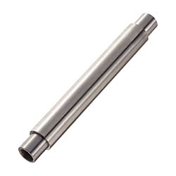
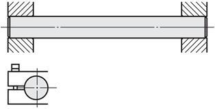
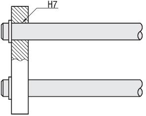
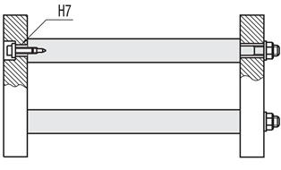
          Linear shafts / stepped on both sides, internal thread

          Artikelnummer:

          Ej färdigt: 20 kandidater hittades.
          Antal:

          Skiss och specifikationstabell

          Back to Linear Shaft Category

          Technical Drawing - Linear Shafts


          Both Ends Stepped and Tapped/Both Ends Stepped:Related Image


          Basic Properties (e.g. material, hardness, coating, tolerance) - Linear Shafts


          TypeMaterialHardness
          Surface Treatment
          Both Ends Stepped and Tapped
          Both Ends Stepped
          D Tol. g6D Tol. h5D Tol. f8D Tol. g6D Tol. h5D Tol. f8
          SFAHSFUH-SFAJSFUJ-EN 1.3505 Equiv.Effective Hardened Depth of Induction Hardening >>P.112
          EN 1.3505 Equiv. 58HRC~
          EN 1.4037 Equiv. 56HRC~
          -
          SSFAHSSFUH-SSFAJSSFUJ-EN 1.4037 Equiv.
          PSFAHPSFUH-PSFAJPSFUJ-EN 1.3505 Equiv.Hard Chrome Plating
          Plating Hardness: HV750 ~
          Plating Thickness: 5µ or More
          PSSFAHPSSFUH-PSSFAJPSSFUJ-EN 1.4037 Equiv.
          RSFAH--RSFAJ--EN 1.3505 Equiv.LTBC Plating
          --PSFGH--PSFGJEN 1.1191 Equiv.-Hard Chrome Plating
          Plating Hardness: HV750 ~
          Plating Thickness: 10µ or More
          --PSSFGH--PSSFGJEN 1.4301 Equiv.


          D Tol.
          Dg6h5f8
          8-0.005
          -0.014
          0
          -0.006
          -0.013
          -0.035
          10
          12-0.006
          -0.017
          0
          -0.008
          -0.016
          -0.043
          13
          15
          16
          18
          20-0.007
          -0.020
          0
          -0.009
          -0.020
          -0.053
          25
          30
          35-0.009
          -0.025
          0
          -0.011
          -0.025
          -0.064
          40
          50

          Further specifications can be found under the tab More Information.


          Composition of a Product Code - Linear Shafts


          Part Number-L-F-P-M-T
          SSFAH18
          SFAH20
          SFAJ20
          -
          -
          -
          200
          400
          400
          -
          -
          -
          F20
          F25
          F25
          -
          -
          -
          P15
          P16
          P16
          -
          -
           
          M8
          M10
           
          -
          -
          -
          T20
          T20
          T20


          Alterations - Linear Shafts


          Both Ends Stepped and Tapped/Both Ends Stepped:Related Image

          You find further options in detail under Option Overview.


          Artikelnummerlista

          Antal artiklar

          Shaft end Shape (Left)

          Shaft end Shape (Right)

          [D] Diameter (Shaft)

          (mm)

          [L] Length (Shaft)

          (mm)

          Material

          Heat Treatment

          Surface Treatment

          ISO Tolerance

          Hardness

          [MD] Size (thread - depth 3xM)

          (mm)

          [F] Length (stud - offset - front side)

          (mm)

          [P] Diameter (stepped - front side)

          (mm)

          [T] Length (stud - stepped - back side)

          (mm)

          [M] Size (thread - depth 2xM)

          (mm)

          RoHS?Minsta beställningsantal
          Internal thread
          Internal thread
          8
          25 ~ 500
          [Alloyed Steel] EN 1.3505 Equiv.
          Induction Hardened
          LTBC Plating
          g6
          Induction Hardening (58HRC~)
          -
          2 ~ 24
          6
          2 ~ 24
          3
          10
          1 stycken
          Internal thread
          Internal thread
          10
          25 ~ 500
          [Alloyed Steel] EN 1.3505 Equiv.
          Induction Hardened
          LTBC Plating
          g6
          Induction Hardening (58HRC~)
          -
          2 ~ 32
          6 ~ 8
          2 ~ 32
          3 ~ 5
          10
          1 stycken
          Internal thread
          Internal thread
          12
          25 ~ 500
          [Alloyed Steel] EN 1.3505 Equiv.
          Induction Hardened
          LTBC Plating
          g6
          Induction Hardening (58HRC~)
          -
          2 ~ 40
          6 ~ 10
          2 ~ 40
          3 ~ 6
          10
          1 stycken
          Internal thread
          Internal thread
          13
          25 ~ 500
          [Alloyed Steel] EN 1.3505 Equiv.
          Induction Hardened
          LTBC Plating
          g6
          Induction Hardening (58HRC~)
          -
          2 ~ 44
          6 ~ 11
          2 ~ 44
          3 ~ 8
          10
          1 stycken
          Internal thread
          Internal thread
          15
          25 ~ 500
          [Alloyed Steel] EN 1.3505 Equiv.
          Induction Hardened
          LTBC Plating
          g6
          Induction Hardening (58HRC~)
          -
          2 ~ 52
          6 ~ 13
          2 ~ 52
          3 ~ 10
          10
          1 stycken
          Internal thread
          Internal thread
          16
          25 ~ 500
          [Alloyed Steel] EN 1.3505 Equiv.
          Induction Hardened
          LTBC Plating
          g6
          Induction Hardening (58HRC~)
          -
          2 ~ 56
          6 ~ 14
          2 ~ 56
          3 ~ 10
          10
          1 stycken
          Internal thread
          Internal thread
          18
          25 ~ 500
          [Alloyed Steel] EN 1.3505 Equiv.
          Induction Hardened
          LTBC Plating
          g6
          Induction Hardening (58HRC~)
          -
          2 ~ 64
          8 ~ 16
          2 ~ 64
          4 ~ 12
          10
          1 stycken
          Internal thread
          Internal thread
          20
          25 ~ 500
          [Alloyed Steel] EN 1.3505 Equiv.
          Induction Hardened
          LTBC Plating
          g6
          Induction Hardening (58HRC~)
          -
          2 ~ 68
          8 ~ 17
          2 ~ 68
          4 ~ 12
          10
          1 stycken
          Internal thread
          Internal thread
          25
          25 ~ 500
          [Alloyed Steel] EN 1.3505 Equiv.
          Induction Hardened
          LTBC Plating
          g6
          Induction Hardening (58HRC~)
          -
          2 ~ 88
          8 ~ 22
          2 ~ 88
          4 ~ 16
          10
          1 stycken
          Internal thread
          Internal thread
          30
          25 ~ 500
          [Alloyed Steel] EN 1.3505 Equiv.
          Induction Hardened
          LTBC Plating
          g6
          Induction Hardening (58HRC~)
          -
          2 ~ 108
          9 ~ 27
          2 ~ 108
          5 ~ 24
          10
          1 stycken
          Straight
          Straight
          8
          25 ~ 500
          [Alloyed Steel] EN 1.3505 Equiv.
          Induction Hardened
          LTBC Plating
          g6
          Induction Hardening (58HRC~)
          -
          2 ~ 24
          6
          2 ~ 24
          -
          10
          1 stycken
          Straight
          Straight
          10
          25 ~ 500
          [Alloyed Steel] EN 1.3505 Equiv.
          Induction Hardened
          LTBC Plating
          g6
          Induction Hardening (58HRC~)
          -
          2 ~ 32
          6 ~ 8
          2 ~ 32
          -
          10
          1 stycken
          Straight
          Straight
          12
          25 ~ 500
          [Alloyed Steel] EN 1.3505 Equiv.
          Induction Hardened
          LTBC Plating
          g6
          Induction Hardening (58HRC~)
          -
          2 ~ 40
          6 ~ 10
          2 ~ 40
          -
          10
          1 stycken
          Straight
          Straight
          13
          25 ~ 500
          [Alloyed Steel] EN 1.3505 Equiv.
          Induction Hardened
          LTBC Plating
          g6
          Induction Hardening (58HRC~)
          -
          2 ~ 44
          6 ~ 11
          2 ~ 44
          -
          10
          1 stycken
          Straight
          Straight
          15
          25 ~ 500
          [Alloyed Steel] EN 1.3505 Equiv.
          Induction Hardened
          LTBC Plating
          g6
          Induction Hardening (58HRC~)
          -
          2 ~ 52
          6 ~ 13
          2 ~ 52
          -
          10
          1 stycken
          Straight
          Straight
          16
          25 ~ 500
          [Alloyed Steel] EN 1.3505 Equiv.
          Induction Hardened
          LTBC Plating
          g6
          Induction Hardening (58HRC~)
          -
          2 ~ 56
          6 ~ 14
          2 ~ 56
          -
          10
          1 stycken
          Straight
          Straight
          18
          25 ~ 500
          [Alloyed Steel] EN 1.3505 Equiv.
          Induction Hardened
          LTBC Plating
          g6
          Induction Hardening (58HRC~)
          -
          2 ~ 64
          8 ~ 16
          2 ~ 64
          -
          10
          1 stycken
          Straight
          Straight
          20
          25 ~ 500
          [Alloyed Steel] EN 1.3505 Equiv.
          Induction Hardened
          LTBC Plating
          g6
          Induction Hardening (58HRC~)
          -
          2 ~ 68
          8 ~ 17
          2 ~ 68
          -
          10
          1 stycken
          Straight
          Straight
          25
          25 ~ 500
          [Alloyed Steel] EN 1.3505 Equiv.
          Induction Hardened
          LTBC Plating
          g6
          Induction Hardening (58HRC~)
          -
          2 ~ 88
          8 ~ 22
          2 ~ 88
          -
          10
          1 stycken
          Straight
          Straight
          30
          25 ~ 500
          [Alloyed Steel] EN 1.3505 Equiv.
          Induction Hardened
          LTBC Plating
          g6
          Induction Hardening (58HRC~)
          -
          2 ~ 108
          9 ~ 27
          2 ~ 108
          -
          10
          1 stycken
          Enhetspris (exklusive MOMS)(Enhetspris inklusive MOMS)
          Standardavsändningsdatum
          -
          ( - )
          12 arbetsdagar
          -
          ( - )
          12 arbetsdagar
          -
          ( - )
          12 arbetsdagar
          -
          ( - )
          12 arbetsdagar
          -
          ( - )
          12 arbetsdagar
          -
          ( - )
          12 arbetsdagar
          -
          ( - )
          12 arbetsdagar
          -
          ( - )
          12 arbetsdagar
          -
          ( - )
          12 arbetsdagar
          -
          ( - )
          12 arbetsdagar
          -
          ( - )
          12 arbetsdagar
          -
          ( - )
          12 arbetsdagar
          -
          ( - )
          12 arbetsdagar
          -
          ( - )
          12 arbetsdagar
          -
          ( - )
          12 arbetsdagar
          -
          ( - )
          12 arbetsdagar
          -
          ( - )
          12 arbetsdagar
          -
          ( - )
          12 arbetsdagar
          -
          ( - )
          12 arbetsdagar
          -
          ( - )
          12 arbetsdagar

          Detaljerad information

          Grundläggande information

          Försiktighet

          • SFAH has been localized according to European needs and requirements. Please have a look on the EU version SFAHEU. SFAHEU is available in EN 1.1213 (Cf53) and h6 / h7.

          Skiss och specifikationer

          Back to Linear Shaft Category

          Technical Drawing - Linear Shafts


          Both Ends Stepped and Tapped/Both Ends Stepped:Related Image


          Specification Tables - Linear Shafts


          Overview of the shaft designs as PDF


          Part Number1mm IncrementM (Coarse)
          Selection
          (Y)Max.RC
          TypeDLF, TP
          Both Ends Stepped and Tapped
          (D Tolerance g6)
          SFAH
          SSFAH
          PSFAH
          PSSFAH
          RSFAH

          (D≤30, L≤500)
          (D Tolerance f8)
          PSFGH
          PSSFGH
          (D Tolerance h5)
          SFUH
          SSFU
          H
          PSFUH

          PSSFUH


          Both Ends Stepped
          (D Tolerance g6)
          SFAJ
          SSFAJ
          PSFAJ
          PSSFAJ
          RSF
          AJ
          (D≤30, L≤500)
          (D Tol. f8)
          PSFGJ
          PSSFGJ
          (D Tolerance h5)
          SFUJ
          SSFUJ
          PSFUJ
          PSSFUJ


          825~7962≤F≤Px4

          2≤T≤Px4
          63          8000.3 or Less0.5 or Less
          1025~7966~8345        800
          1225~9966~103456       1000
          1325~9966~1134568      1000
          1525~9966~133456810     1000
          1625~11966~143456810     1200
          1825~11968~16 45681012    1200
          2025~11968~17 45681012    12001.0 or Less
          2525~11968~22 4568101216   1200
          3025~14969~27  5681012162024 1500
          3525~14969~32  5681012162024 15000.5 or Less
          4025~149611~37   681012162024301500
          5025~149611~47   681012162024301500
          • Both Ends Tapped P dimensions require M+3≤P. When (Mx2.5+4)x2≥(Y), tap pilot hole may go through.


          Alterations - Linear Shafts


          Both Ends Stepped and Tapped/Both Ends Stepped:Related Image

          You find further options in detail under Option Overview.

          Surface Limits / Hardness - Linear Shafts


          Limits of hardness and hardening depth

          The linear shafts are processed after the base material has undergone inductive hardening. Therefore, the processed surfaces may result in a deviating hardness.
          In the following example, you can view the affected areas of the linear shaft, which may be affected after processing by e.g. threads, level surfaces, key surfaces and transverse bores.


          Limitation of linear shaft induction hardening


          Cause for deviating hardness

          The raw material of the linear shaft is treated via thermal induction before grinding. Thus, a configured linear shaft can be custom-made not only cost-effectively, but also with short delivery times. The linear shaft is hardened at the boundary layer (boundary layer hardening) of the liner shaft. The depth of the hardened boundary layer depends on the material used and the diameter of the linear shaft. The following table shows the hardening depth of linear shafts.
          Coatings and plating are applied to the raw material after hardening and grinding. For more information, see Coatings of the Linear Shaft.


          Boundary layer hardening of a linear shaft

          Figure of boundary layer hardening: hardened boundary layer in light gray


          Effective hardening depth of linear shafts

          Outside diameter (D)Effective hardening depth
          EN 1.1191 equiv.EN 1.3505 equiv.EN 1.4125 equiv.EN 1.4301 equiv.
          3-+0.5+0.5Without induction hardening
          4-
          5-
          6 - 10+0.3
          12 - 13+0.5+0.7+0.5
          15 - 20+0.7
          25 - 50+0.8+1

          Overview of the effective hardening depth as PDF


          Coatings of the linear shaft

          The surface coating is applied to the raw material before machining the linear shaft. Thanks to their coating, the usable surface or work surface of the linear shaft is not only protected against corrosion but also against wear.
          Machined positions of the linear shafts, such as plane surfaces or threads, may be uncoated, as they are added afterwards. This can lead to the machined surfaces being corroded in a linear shaft made of steel. If the linear shaft is used in a corrosive environment, it is recommended to use a stainless steel linear shaft.
          The following figure shows the areas of the linear shaft that are coated (crosshatched). 


          Surface coating after processing the linear shaft

          Figure: Coating of linear shafts


          You can find further information on surface treatment and hardness in this PDF .


          General Information - Linear Shafts


          Linear Shaft Selection Details

          - Material: steel, stainless steel

          - Coating/plating: uncoated, hard chrome plated, LTBC coated, chemically nickel-plated

          - Heat treatment: untreated, inductively hardened

          - ISO tolerances: h5, k5, g6, h6, h7, f8

          - Precision classes: perpendicularity 0.03, concentricity (with thread and increments) Ø0.02, perpendicularity 0.20, concentricity (thread and stepper) Ø0.10

          - Linearity/roundness: depends on diameter, here for the PDF


          Description / basics of the linear shaft

          Linear shafts are steel shafts that perform guiding tasks in combination with linear bearings, such as plain bearing bushings or linear ball bushings. Linear shaft holding functions can be adopted from shaft holders or linear ball bearing adapters. Most linear shafts are heat-treated (induction hardened) solid shafts. A special design of linear shafts is the hollow shaft, which is also called tubular shaft. Inductively hardened linear shafts have a high surface hardness and a tough core. The achievable surface hardness is approx. 55-58 HRC (see information on hardening depth). Linear shafts made of stainless steels can generally not be hardened. Therefore, these steel shafts should be chrome plated to protect them from wear.


          Materials

          Linear shafts are mainly hardened steel shafts. In addition to the selected heat treatment, the steel used in particular imparts its properties to the linear shaft, although it is a hollow shaft or a solid shaft. Therefore, special aspects such as hardness, corrosion and wear must be considered when selecting the shaft steel.


          Coatings

          To protect linear shafts from corrosion, the surface can be chemically nickel-plated. As an alternative to chemical nickel-plating, steel shafts can also be coated with LTBC. The LTBC coating is an anti-corrosive surface coating and it is a low-reflection coating, made of a 5 μm thick film of fluoropolymer, which in essence is a black film. In addition, the LTBC coating is resistant to bursting pressure by extreme or repeated bending. LTBC-coated linear shafts are thus particularly suitable for locations where corrosion or light reflections are undesirable. Linear shafts that require particularly high surface hardness and wear resistance can be hard chrome plated.


          Function

          The form and function of linear shafts differ from linear guiderails. Linear guiderails are square rails that work in combination with carriers (rotary elements, carriages) according to the rolling or sliding principle. Linear shafts on the other hand are precision-ground round steel shafts that take on a linear guide function in conjunction with linear ball bushings or plain bearing bushings (maintenance-free bushings).


          Areas of Application

          Linear shafts are intended for axial motion. Whether horizontal or vertical linear motion, all linear motions can be implemented with linear shafts. Common applications are stroke mechanisms and other applications with high demands on smoothness, precision and service life. Linear shafts can therefore be used in almost all industries of plant construction and mechanical engineering. Linear shafts are often found in 3D printers, metering equipment, measuring devices, positioning devices, alignment devices, bending devices and sorting equipment.


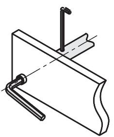
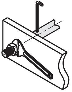
          Instructions for Use / Installation  - Linear Shafts


          For product selection, please observe the linear shaft tolerances (e.g. h5, k5, g6, h6, h7, f8) in conjunction with the diameter tolerance of the plain bearing bushing (sliding bearing) after pressing in or the running circle diameter of the linear ball bearing (ball bushing).


          Diameter change of linear ball bushings after pressing  Inner diameter of linear ball bushings or ball bushings


          Shaft Fasteners


          Application Example of a Linear Shaft - Linear Shafts with Linear Ball Bushings - Linear Shafts with Shaft Holder
          Application Example of a Linear Shaft Application Example - Linear Shaft with Linear Ball Bearings - Linear Ball Bearings with an Adjusting Ring
          Application Example of a Linear Shaft - Linear Shaft with Shaft Holder
          Application Example of a Linear Shaft - Linear Shaft with Circlip Groove - Linear Shaft with Circlip
          Application Example of a Linear Shaft - Linear Shaft with Holding Washer
          Application Example of a Linear Shaft - Linear Thread - Outer Threaded Linear Shaft - Linear Threaded with inner and outer threads
          Application Example of a Linear Shaft - Cross Bore Linear Shaft - Inner Thread Linear Shaft
          Application Example of a Linear Shaft - Cross Bore Linear Shaft - Outer Thread Linear Shaft


          Supplementary Article


          Shaft holder

          Product range of shaft holders


          Adjusting rings/clamping rings

          Product range of adjusting rings - product range of clamping rings


          Linear ball bearing

          Product range of linear ball bearings - product range of ball sleeves - linear ball bearing with housing


          Plain bearing bushings

          Product range of sliding bearing bushings - plain bearing with housing


          Ball guides

          Ball guide product range


          Industrial Applications


          3D printer industry
          3D printer industry
          Automotive industry
          Automotive industry
          Pharmaceutical industry
          Pharmaceutical industry
          Packaging industry
          Packaging industry