- Belt Width (mm)(mm)
- 6
- 6.4
- 7.9
- 9.5
- 10
- 12.7
- 15
- 19.1
- 20
- 25
- 25.4
- 30
- 38.1
- 40
- Belt Width (Inch)(Inch)
- 0.25
- 0.31
- 0.37
- 0.5
- 0.6
- 0.75
- 1
- 1.5
- 2
- 2.5
- 3
- 4
- A(mm)[25-150/1mm units]
- B(mm)[12-60/1mm units]
- C(mm)[12-50/1mm units]
- L(mm)[30-250/1mm units]
- S(mm)[11-45/1mm units]
- Z
- 3
- 4
- 5
- 6
- Type
- CAD
- 3D
- Uppskattade leveransdagar
- Alla
- Inom 9 arbetsdagar
Timing belt connecting plates / XL, L, T5, S#M / aluminium

Artikelnummer:
kandidater hittades.Skiss och specifikationstabell

■ Accuracy Standards
● Flatness: 0.4 or Less per 1,000 mm
● Tolerance of Plate Thickness ±0.04 for 6
±0.05 for 8

[ ! ]A groove for overpressure prevention is provided to prevent a belt from being excessively clamped.

| Recommended Combinations | ||
| Type | Belt Type | Applicable Linear Guide |
| TBLG | S3M | Miniature Linear Guides |
| S5M | Miniature Linear Guides Linear Guides for Medium Load | |
| T5 | ||
| XL | ||
| L | Linear Guides for Medium Load Linear Guides for Heavy Load | |
| S8M | ||
| Counterbored Hole | |||||||||||||||||||||||||||||||||||||||||||
| Z·Z1 | |||||||||||||||||||||||||||||||||||||||||||
 Z1 Counterbore Dimension on Belt Mounting Side
Z: Counterbore Dimension on Guide Pushing Side
| |||||||||||||||||||||||||||||||||||||||||||
| Type | [M] Material | [S] Surface Treatment | Number of Workpiece Mounting Holes |
| TBLG | EN AW−5052 Equiv. | Clear Anodize | 6 |
| [A] Accessory | [M] Material | Qty. |
| Timing Belt Clamp Plates | EN AW−6061 Equiv. | 1 |
| Extra Low Head Cap Screw (for Belt Mounting): CBSTS | EN 1.4301 Equiv. | 4 |
Specification Table
1.: Specify the type and width of belt.
2.: Specify the A dimension (plate width), L dimension (center distance between Linear Guide and Timing Belt) and S dimension (Depth of Clamp Plate toward the Linear Guide Center).
3.: Specify the B/C dimension (mounting hole pitch for Linear Guide) and the Z dimension (counterbore nominal dia. for Linear Guide-mounting screw). Specify the hex socket head cap screw to fit the mounting hole (counterbored hole) of Linear Guide.
[ ! ] Linear Guide-mounting screws are not included.
Ordering Example
| Part Number | — | A | — | L | — | S | — | B | — | C | — | Z |
| TBLGXL050 | — | 50 | — | 100 | — | 24 | — | 35 | — | 35 | — | 6 |
| Type | Applicable belts | Dimension Configurable (1 mm Increments) | Fixed Dimension | |||||||||||||||
| Plate | Linear Guide-mounting Hole | Guide Side | Belt Side | |||||||||||||||
| Belt Type | Nominal Width | A | L | S | B | C | Z (Counterbored Hole) | T | M (Tapped Hole) | P | G | K | Z1 (Counterbored Hole) Screw Nominal | T1 | (Referential Info) Belt Width | |||
| TBLG | XL | 025 | 36 to 90 | 50 to 250 | 11 to 45 | 12 to 60 | 12 to 50 | 3·4·5·6 | T: 6 (Z=3·4 selected) T: 8 (Z=5·6 selected) | M=Z | 13 | 25 | 12 | 4 | 2.1 | 6.4 | ||
| 031 | 14 | 12.5 | 7.9 | |||||||||||||||
| 037 | 16 | 13 | 9.5 | |||||||||||||||
| 050 | 20 | 15 | 12.7 | |||||||||||||||
| L | 050 | 66 to 125 | 55 to 250 | 15 to 45 | 17 to 60 | 17 to 50 | 5·6 | 21 | 50 | 16 | 5 | 3.3 | 12.7 | |||||
| 075 | 27 | 19 | 19.1 | |||||||||||||||
| 100 | 34 | 23 | 25.4 | |||||||||||||||
| 150 | 46 | 29 | 38.1 | |||||||||||||||
| S3M | 060 | 25 to 90 | 30 to 150 | 11 to 45 | 12 to 28 | 12 to 35 | 3·4·5·6 | 11 | 15 | 10 | 3 | 1.9 | 6 | |||||
| 100 | 15 | 12.5 | 10 | |||||||||||||||
| 150 | 20 | 15 | 15 | |||||||||||||||
| S5M | 100 | 37 to 100 | 50 to 250 | 15 to 45 | 17 to 60 | 17 to 50 | 5·6 | 17 | 25 | 13 | 4 | 3.1 | 10 | |||||
| 150 | 22 | 16 | 15 | |||||||||||||||
| 250 | 32 | 21 | 25 | |||||||||||||||
| S8M | 150 | 56 to 150 | 60 to 250 | 15 to 45 | 17 to 60 | 17 to 50 | 5·6 | 23 | 40 | 17 | 5 | 4.7 | 15 | |||||
| 250 | 33 | 22 | 25 | |||||||||||||||
| 300 | 38 | 25 | 30 | |||||||||||||||
| 400 | 48 | 30 | 40 | |||||||||||||||
| T5 | 100 | 35 to 100 | 50 to 250 | 11 to 45 | 12 to 60 | 12 to 50 | 3·4·5·6 | 17 | 25 | 13 | 4 | 2.2 | 10 | |||||
| 150 | 22 | 16 | 15 | |||||||||||||||
| 200 | 27 | 19 | 20 | |||||||||||||||
| 250 | 32 | 21.5 | 25 | |||||||||||||||
| [ ! ]W=L+K+S [ ! ] AC - Zd1 ≥ 2 [ ! ] L-B-P/2-Z1 d1/2-M/2 ≥ 1 | [ ! ] B (C)-Zd1-M ≥ 2 [ ! ] SB/2-Zd1/2 ≥ 1 [ ! ]L ≥ A | |||||||||||||||||
| Accessory | |||||||||||
| Timing Belt Clamp Plates | Extra Low Head Cap Screw | ||||||||||
| Belt Type | Nominal Width | Belt Width | AT | BT | TT | h | P | G | M | For T = 6 | For T = 8 |
| XL | 025 | 6.4 | 36 | 24 | 6 | 1.30 | 13 | 25 | M4 | CBSTS4-10 | CBSTS4-12 |
| 031 | 7.9 | 25 | 14 | ||||||||
| 037 | 9.5 | 26 | 16 | ||||||||
| 050 | 12.7 | 30 | 20 | ||||||||
| L | 050 | 12.7 | 66 | 32 | 8 | 2.05 | 21 | 50 | M5 | - | CBSTS5-12 |
| 075 | 19.1 | 38 | 27 | ||||||||
| 100 | 25.4 | 46 | 34 | ||||||||
| 150 | 38.1 | 58 | 46 | ||||||||
| S3M | 060 | 6 | 21 | 18 | 4 | 1.25 | 11 | 15 | M3 | CBSTS3-8 | CBSTS3-10 |
| 100 | 10 | 22 | 15 | ||||||||
| 150 | 15 | 28 | 20 | ||||||||
| S5M | 100 | 10 | 35 | 26 | 6 | 2.00 | 17 | 25 | M4 | - | CBSTS4-12 |
| 150 | 15 | 32 | 22 | ||||||||
| 250 | 25 | 42 | 32 | ||||||||
| S8M | 150 | 15 | 56 | 34 | 8 | 3.00 | 23 | 40 | M5 | CBSTS5-14 | |
| 250 | 25 | 44 | 33 | ||||||||
| 300 | 30 | 50 | 38 | ||||||||
| 400 | 40 | 60 | 48 | ||||||||
| T5 | 100 | 10 | 35 | 26 | 6 | 1.40 | 17 | 25 | M4 | CBSTS4-10 | CBSTS4-12 |
| 150 | 15 | 32 | 22 | ||||||||
| 200 | 20 | 38 | 27 | ||||||||
| 250 | 25 | 43 | 32 | ||||||||
Alterations
| Alterations Code | Alteration Details | Application Notes | Ordering Example | |||||||||||
| MH | Changes the Tapped Hole Dia. on the Linear Guide Mounting Side | Change the Tapped Hole Dia. from Z (Counterbore Nominal Dia.) = M. [Ordering Code]MH3
| "!" When MH and MT are combined: MT is applied to 2 places on the plate center. MH is applied to 4 places on portions other than Plate Center. [ ! ] B (C)-Zd1-MH ≥ 2 | TBLGXL050-50-100-24-35-35-6-MH4 | ||||||||||
| MT | Changes the dia. of each of two tapped holes on the Plate Center | Out of 6 tapped holes on Linear Guide Mounting Side, 2 tapped holes located on Plate Center are changed to the other hole dia. [Ordering Code]: MT2
| "!" When MH and MT are combined: MT is applied to 2 places on the plate center. MH is applied to 4 places on portions other than Plate Center. [ ! ] B (C)-Zd1-MT ≥ 2 | TBLGXL050-50-100-24-35-35-6-MT2 | ||||||||||
Artikelnummerlista
| Artikelnummer |
|---|
Enhetspris (exklusive MOMS)(Enhetspris inklusive MOMS) | Standardavsändningsdatum |
|---|
- ( - ) | 9 arbetsdagar |
- ( - ) | 9 arbetsdagar |
- ( - ) | 9 arbetsdagar |
- ( - ) | 9 arbetsdagar |
- ( - ) | 9 arbetsdagar |
- ( - ) | 9 arbetsdagar |
- ( - ) | 9 arbetsdagar |
- ( - ) | 9 arbetsdagar |
- ( - ) | 9 arbetsdagar |
- ( - ) | 9 arbetsdagar |
- ( - ) | 9 arbetsdagar |
- ( - ) | 9 arbetsdagar |
- ( - ) | 9 arbetsdagar |
- ( - ) | 9 arbetsdagar |
- ( - ) | 9 arbetsdagar |
- ( - ) | 9 arbetsdagar |
- ( - ) | 9 arbetsdagar |
- ( - ) | 9 arbetsdagar |
- ( - ) | 9 arbetsdagar |
- ( - ) | 9 arbetsdagar |
- ( - ) | 9 arbetsdagar |
- ( - ) | 9 arbetsdagar |
Detaljerad information
Grundläggande information
Skiss och specifikationer
App. Example


General Information - Timing Belts

Timing Belt Selection Details
- Material: chloroprene rubber (neoprene), polyurethane (PU)
- Tension cord: glass fibre, aramid fibre, steel
- Width (mm): 1 to 101.6
- Width (in.): 0.19 to 4
- Profile (metric): T5, T10, AT5, AT10, S2M, S3M, S5M, S8M, S14M, MTS8M, EV5GT, EV8YU, 2GT, 3GT, MA3, MA5, MA8, P2M, P3M, P5M, P8M, UP5M, UP8M
- Profile (in.): MXL, XL, L, H
Description/Basics
Timing belts for mechanical engineering are intended for force and power transmission. Depending on the interlocking of the profile, they can alternatively be used for the material flow (transportation) or for positioning.
Timing belts are more maintenance-friendly, efficient and durable compared to roller chains.
Maintenance-friendly: timing belts do not require lubrication, are easy to replace and are very durable, as they do not sag. These properties significantly reduce maintenance costs.
Efficient: drive belts are largely made of natural rubber or polyurethane. As a result, timing belts withstand high speeds. A further advantage of these materials is the weight reduction compared to conventional metal drives. Timing belts are also known for low-noise running and contribute to the general smooth running of an application.
Durability: due to the inserted tension cord made of glass fibre or aramid fibre (Kevlar), timing belts can withstand high tensile stresses and do not tend to sag. An additional layer of nylon fabric on the interlocked side reduces wear due to abrasion and increases the service life.
Timing belts can be used in many ways. The belt profile that suits your application depends on the task of the timing belt. MISUMI offers a suitable belt profile for almost every type of application.
Drive: timing belts are used even at high torque. Drive belts with a rounded trapezoidal profile (e.g., S8M) are often used to drive mechanical components. These are particularly well suited for slip-free transmission of high forces, which can occur in drives of various applications or machines.
Positioning: a semi-circular profile (e.g., GT) is often used for positioning via timing belts. Round profile timing belts are often used in 3D printers and precise scanners. The round shape also offers the advantage that there is little play (reverse play) when the direction changes.
Material flow: timing belts can also be used to transport loads in conveyor systems. A straight trapezoidal profile is often used for this purpose (e.g., AT ). This profile provides a large profile area for load intake and transmission. The MISUMI range also includes conveyor timing belts with nylon fabric on the bearing surface.
An overview of the profile forms by application type can be found in the PDF Overview.
The amount of transmission power depends on many factors. The exact maximum load must be considered and calculated individually according to the application. The calculation for timing belts can be found in the selection of Timing Belts as PDF.
In order not to fall below the minimum number of teeth, the minimum size of the timing pulleys should be considered individually.
In general, a timing belt should be provided with the appropriate pretension to maximize the service life of the timing belt. If the pretension is too low, a jump (slip) can cause wear of the timing belt.
Application Examples - Timing Belts

Application example: workpiece carrier
(1) Stopper bolt with rubber, (2) belt conveyor, (3) workpiece carrier
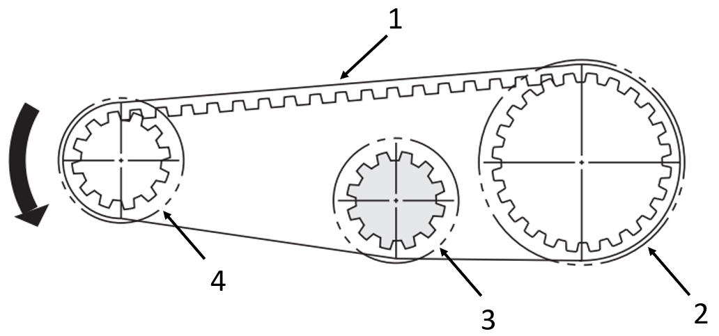
Application example: of toothed belt drives
(1) Toothed belt, (2) driven Timing pulleys with crimp disc, (3) idler pulley with crimp disc, (4) driving Timing pulleys with crimp disc
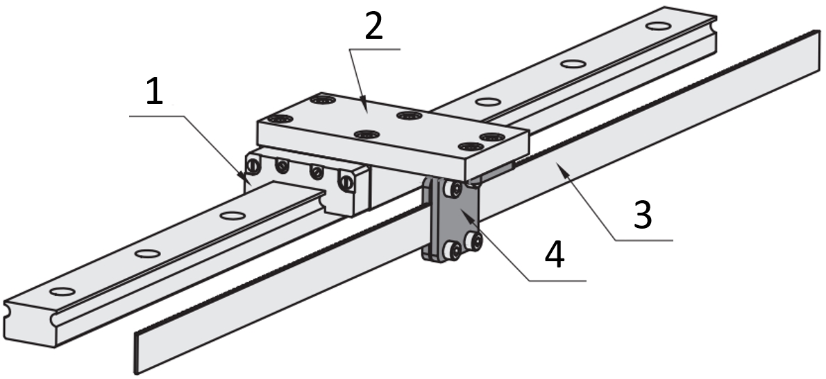
Application example: Timing belt
(1) Linear guide, (2) mounting plate, (3) Timing belt, (4) Screw-on terminal
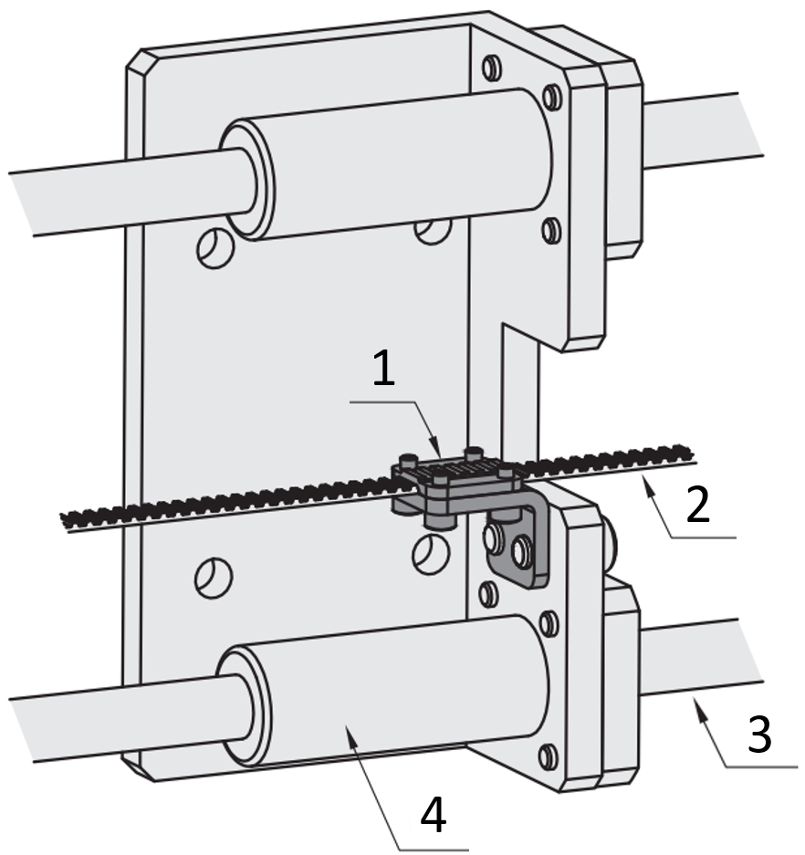
Application example: Timing belt
(1) Bolt-on terminal, (2) Timing belt, (3) Linear shaft, (4) Linear bushings
Industrial Applications


