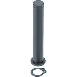
Hinge pins / stainless steel, steel / free choice of end shape / free choice of tolerance (Part Numbers - CAD Download)
- Volume Discount
- Order quantities extended (D-JIT)
Part Number
Once your search is narrowed to one product,
the corresponding part number is displayed here.
- Drawing / Specifications
- 3D Preview 3D preview is available after complete configuration
- Part Numbers
- More Information
- Catalog
Back to the Category Hinge Pin
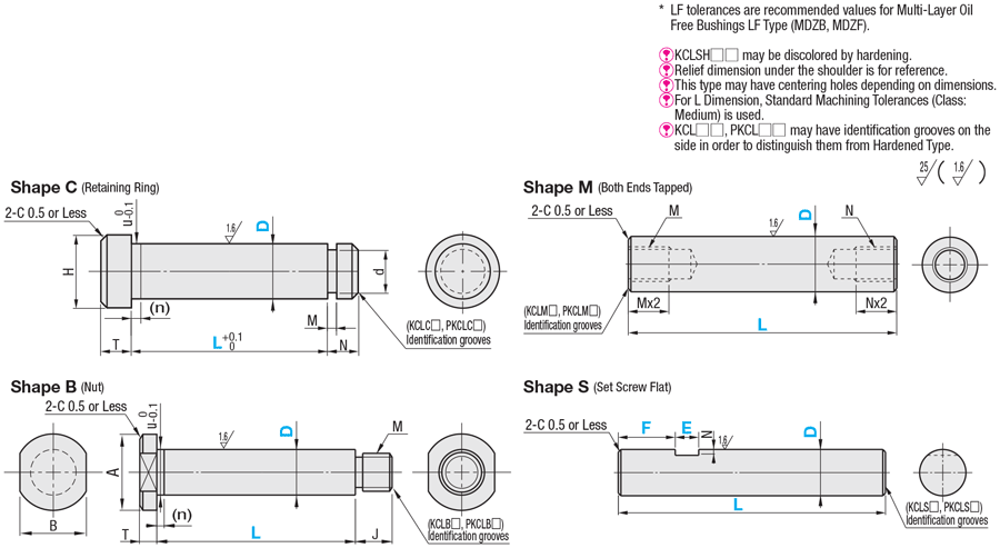
Available dimensions and tolerances can be found under the tab More Information.
| Type | Material | Hardness | Surface Treatment | Accessory | Accessory | ||
| Shape C (Retaining Ring) | Shape B (Nut) | ||||||
| KCL□□ | EN 1.1191 Equiv. | - | Black Oxide | Retaining Ring 1 pc. | Spring Steel | Nut 1 pc. | JIS-SWRCH |
| KCLH□□ | 40~45HRC | ||||||
| PKCL□□ | - | Electroless Nickel Plating | EN 1.4301 Equiv. | EN 1.4301 Equiv. | |||
| PKCLH□□ | 40~45HRC | ||||||
| KCLS□□ | EN 1.4301 Equiv. | - | - | EN 1.4301 Equiv. | EN 1.4301 Equiv. | ||
| KCLSH□□ | EN 1.4125 Equiv. | 45~50HRC | - | EN 1.4301 Equiv. | EN 1.4301 Equiv. | ||
Further specifications can be found under the tab More Information.
| Part Number | - | L | - | F | - | E | ||||
| Type | D Tolerance Selection | D | ||||||||
| KCLC | M | 15 | - | 120.3 | ||||||
| KCLS | F | 15 | - | 50.5 | - | F0 | - | E10 | ||

Hinge Bolt Selection Details
- Material: steel, stainless steel
- Coatings: untreated, burnished, nickel-plated, hard chrome-plated
- ISO tolerances: g6, m6, p6, h7, f8, c9
- Outer diameter: 2 mm to 30 mm
- Length: 5 mm to 200 mm
- End forms: external thread, internal thread, flat surface, hexagon socket, shoulder, flattened shoulder, retaining ring groove, cross holes for cotter pin, spring groove, V-groove
Description/Basics
Hinge bolts for mechanical engineering serve as a movable connecting element and pivot point between two assembly parts. Therefore, knuckle pins enable assembly parts to pivot, similar to a hinge. Furthermore, a hinge pin enables the connection of assembly parts in movable mechanisms, in which they can also serve for example as angular compensation in addition to their connecting function.
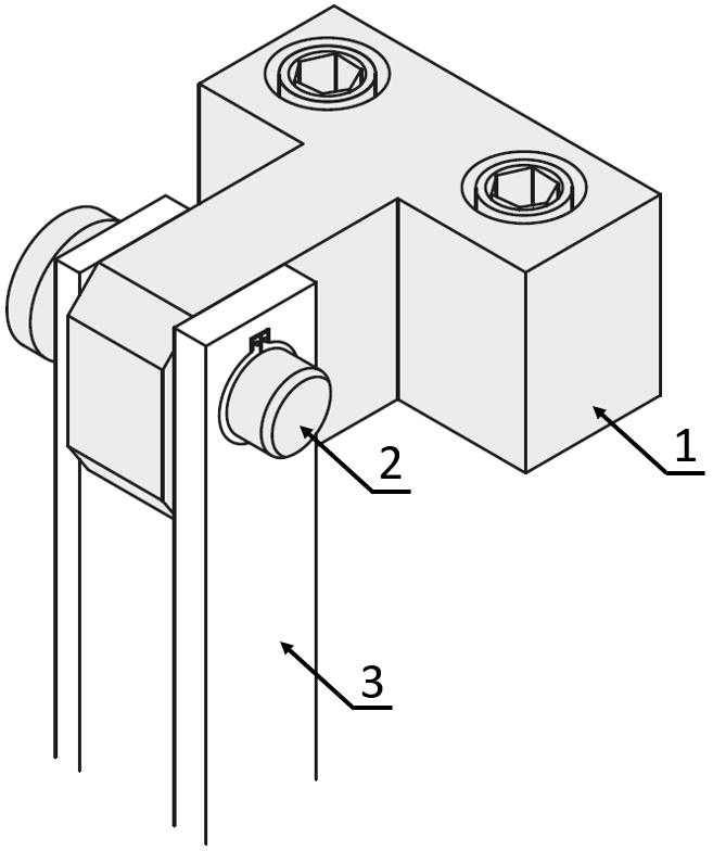
Application example: hinge bolts with retaining ring – (1) hinge base, (2) plug-in bolts with retaining ring, (3) link
In the case of knuckle pin connections, there should be play between the plug-in bolt and the receptacle (bore hole, eyelet, etc.) on the attachment parts in order to ensure smooth rotation. The clearance should be selected depending on the application and load. The most common tolerance is an H7 hole in conjunction with a g6 hinge pin, which is selected for most applications. In addition to tolerance g6, MISUMI also offers knuckle pins in tolerances m6, p6, h7, f8, c9 (type KCL). By selecting the tolerance of the plug-in bolt, the required clearance can be adapted to the respective requirement without having to change the tolerance of the bore hole/eyelets.
Bolts exposed to high motion cycles are subject to increased wear, which can be higher depending on the load applied. Due to abrasion, the play between the hinge bolt and the bore hole/eyelet can increase and lead to inaccuracies in the application.
MISUMI offers hinge bolts with hard chrome plating for particularly high stress. This knuckle pin surface treatment has a high surface hardness and thus a high wear resistance, which ensures an increased durability and requires less maintenance.
MISUMI offers various fasting options for retaining pins.
Hinge bolts with a flat surface on both sides are firmly connected to the hinge base via a set screw. Due to this rigid connection, the hinge pin is not mounted in a rotating manner, which specifically prevents wear on the hinge base.
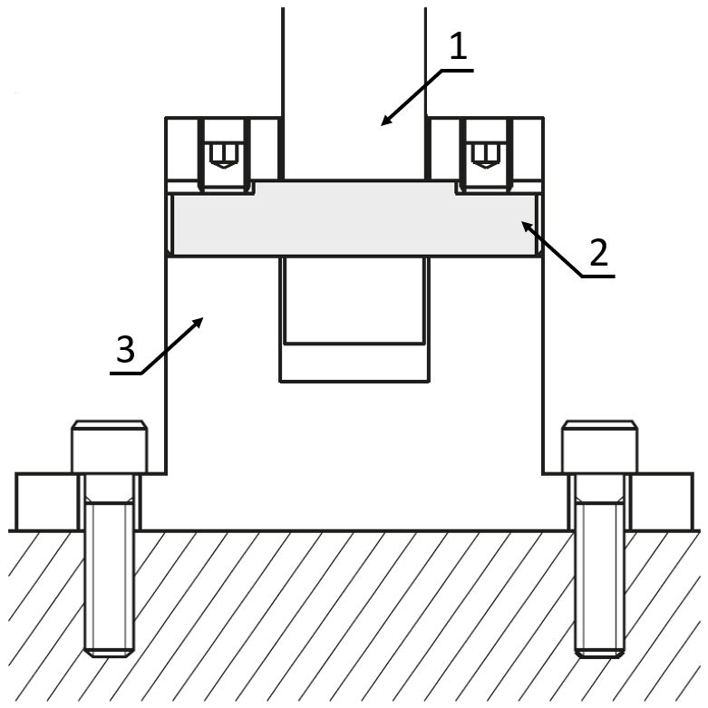
Application example: hinge bolts with flat surfaces - (1) link, (2) plug-in bolts with flat surfaces, (3) hinge base
Bolts with cotter pins are suitable for applications that require a simple replacement of the parts. The very easy-to-lock cotter pins enable quick assembly and disassembly of the hinge bearing, hinge base or cotter pin by means of one or two cotter pins.
Care should be taken to ensure that no strong axial movements and forces occur when using a bolt with cotter pins. If strong forces are applied to the cotter pin, they can shear off and the cotter pins can detach from the connection.
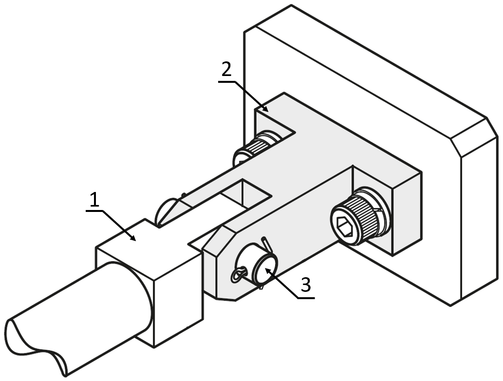
Application example: cotter pins – (1) knuckle joint, (2) hinge base, (3) cotter pin bolts
A commonly used version of the knuckle pins are hinge bolts with retaining ring. This type of connection can be used in almost any application and is typically only loosened after assembly for maintenance purposes.
MISUMI offers the hinge bolts with retaining ring groove with up to four retaining ring grooves. The diameter of our plug-in bolts are selectable and can be configured in length. Therefore, they can be adjusted to your individual needs.

Application example: hinge bolt with retaining ring - (1) mounting plate, (2) roller bearing, (3) knuckle pin with retaining ring, (4) retaining ring
Hinge bolts with head, also called bolts with head or plug-in bolts with shoulder, have the advantage that there is no need for a lock on the side of the head. The head serves as a stop for the plug-in bolt, which can be fitted with a hexagon socket or wrench flat as a drive.
However, the bolts with head can only be assembled and disassembled from one side. This characteristic must be observed during construction and maintenance.
With MISUMI, the shoulder thickness of the hinge bolt can be configured in 0.5 mm increments using the [TC] option. With the option [HC], a flat surface can be attached to the shoulder, which can serve as an anti-rotation device.

Drawing: bolts with head
If a particularly high level of roundness is required, rotary shafts can be used. MISUMI rotary shafts have a roundness of ~ 0.007 to 0.004.
Function
Hinge bolts, also known as knuckle pins, belong to the group of machine and fastening elements. As the centre of a rotating joint, they generally connect two components via eyelets. Hinge bolts can be used among other things to attach doors, windows and flaps in a movable manner. This requires play between the hinge pin and the eyelet, which in most cases is constructed from the combination of an H7 bore hole and a g6 knuckle pin.
Areas of Application
MISUMI hinge bolts and plug-in bolts are indispensable for mechanical engineering and plant engineering, since hinge bolts allow a movable connection used in many applications.
Hinge bolts can be used for hinge mechanisms as in a typical hinge for windows, valves in industrial systems and doors of electrical up to a movable connection elements for links and knuckle joints.
Through our wide selection of end shapes, MISUMI knuckle pins offer versatile applications across various industries.
Materials
MISUMI socket pins are available in steel and stainless steel. As an option, our hinge bolts and socket pins are also available hardened. colour variations may occur with hardened hinge bolts.
Coatings
MISUMI hinge bolts are available in untreated, burnished, nickel-plated and hard chrome-plated versions to protect them from corrosion and wear.
The hard chrome plating offers knuckle pins a high surface hardness and thus a high wear resistance. Plug-in bolts with hard chrome plating help to achieve a high durability and reduced maintenance effort.
Dimensions
Head shapes
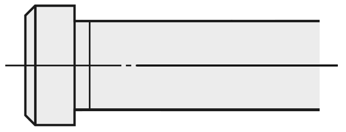
Shoulder
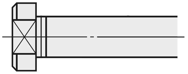
Shoulder with spanner flat

Hexagon socket
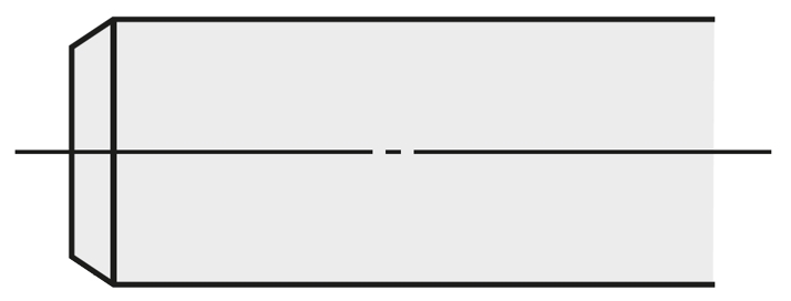
Straight
Installation Information
Hinge bolts can be secured against loss in different ways. At MISUMI, you will find a variety of different knuckle pins.
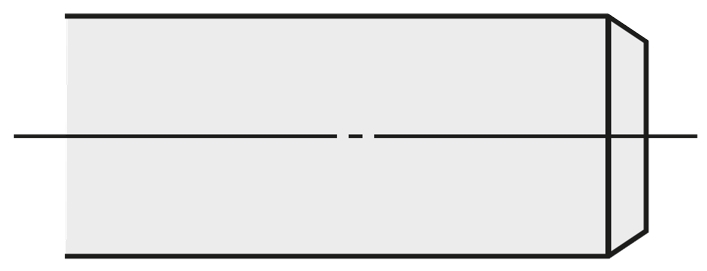
Straight
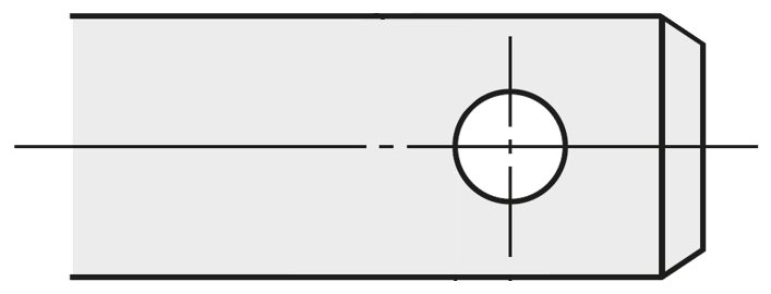
Cotter pin holes
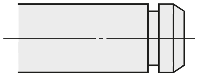
Retaining ring groove
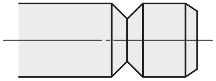
V-groove
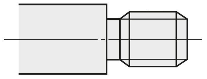
External thread
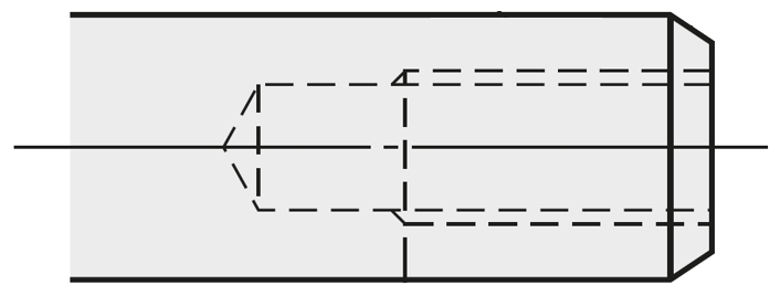
Internal thread

Spring groove
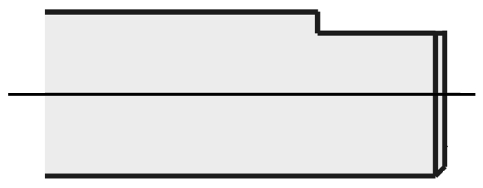
Flat surface
Maintenance
Lubrication
Hinge bolts should be lubricated at regular intervals to prevent wear and to ensure smooth operation. For stroke or folding mechanisms, a long-term grease can be used for the plug-in bolts, as the movements are generally slow. Graphite oil or graphite spray can be used for flaps and doors, as this ensures good long-term lubrication even under high loads. In addition, this type of lubrication is often used with maintenance-free plain bearing bushings. Hinge bolts can also be combined with maintenance-free plain bearing bushings to extend the maintenance intervals.
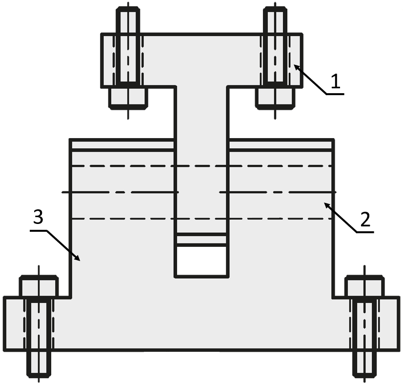
Application example for hinge bolts
(1) Knuckle joint, (2) Plug-in bolts, (3) Hinge base
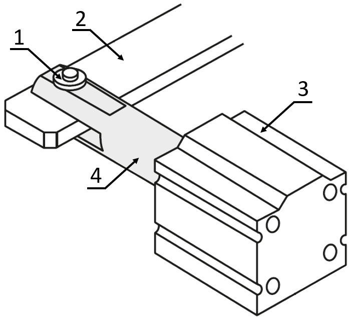
Application example for hinge bolts
(1) Hinge bolt, (2) Link, (3) Air cylinder, (4) Knuckle joint
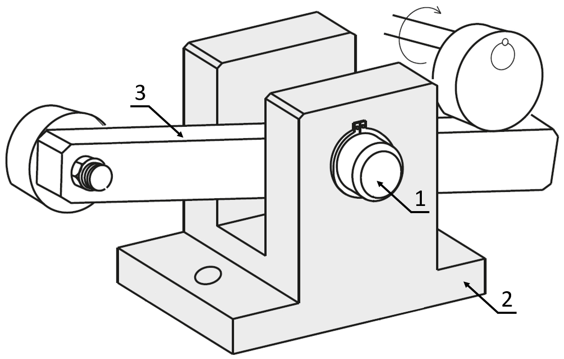
Application example: hinge bolts with retaining ring
(1) Bolts with retaining ring, (2) Hinge base, (3) Link
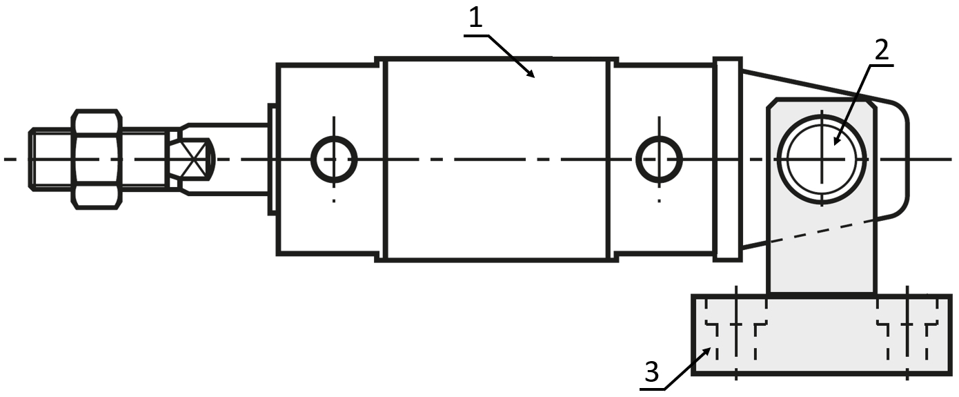
Application example for hinge bolts
(1) Air cylinder, (2) Hinge bolt, (3) Hinge base


Rod end bearings, spherical bearing


Part Number:
- In order to open the 3D preview, the part number must be fixed.
3D preview is not available, because the part number has not yet been determined.
| Part Number |
Standard Unit Price
| Minimum order quantity | Volume Discount | RoHS | Basic Shape | Fastening Method | [D] Shaft Diameter (mm) | Material | Hardness | Surface Treatment | Material Detail | D Tolerance Selection | L Dimension (mm) | E (mm) | F (mm) | |
|---|---|---|---|---|---|---|---|---|---|---|---|---|---|---|---|---|
- | 1 | 4 Days | 10 | Straight | Set Screw/D-Cut | 12 | Stainless Steel | With Hardness | Not Provided | EN 1.4125 Equiv. | LF (for Bushings) | 15 ~ 200 | 1 ~ 50 | 0 ~ 100 | ||
- | 1 | 4 Days | 10 | Straight | Set Screw/D-Cut | 13 | Stainless Steel | With Hardness | Not Provided | EN 1.4125 Equiv. | LF (for Bushings) | 25 ~ 200 | 1 ~ 50 | 0 ~ 100 | ||
- | 1 | 4 Days | 10 | Straight | Set Screw/D-Cut | 14 | Stainless Steel | With Hardness | Not Provided | EN 1.4125 Equiv. | LF (for Bushings) | 25 ~ 200 | 1 ~ 50 | 0 ~ 100 | ||
- | 1 | 4 Days | 10 | Straight | Set Screw/D-Cut | 15 | Stainless Steel | With Hardness | Not Provided | EN 1.4125 Equiv. | LF (for Bushings) | 25 ~ 200 | 1 ~ 50 | 0 ~ 100 | ||
- | 1 | 4 Days | 10 | Straight | Set Screw/D-Cut | 16 | Stainless Steel | With Hardness | Not Provided | EN 1.4125 Equiv. | LF (for Bushings) | 30 ~ 200 | 1 ~ 50 | 0 ~ 100 | ||
- | 1 | 4 Days | 10 | Straight | Set Screw/D-Cut | 17 | Stainless Steel | With Hardness | Not Provided | EN 1.4125 Equiv. | LF (for Bushings) | 30 ~ 200 | 1 ~ 50 | 0 ~ 100 | ||
- | 1 | 4 Days | 10 | Straight | Set Screw/D-Cut | 18 | Stainless Steel | With Hardness | Not Provided | EN 1.4125 Equiv. | LF (for Bushings) | 30 ~ 200 | 1 ~ 50 | 0 ~ 100 | ||
- | 1 | 4 Days | 10 | Straight | Set Screw/D-Cut | 20 | Stainless Steel | With Hardness | Not Provided | EN 1.4125 Equiv. | LF (for Bushings) | 30 ~ 200 | 1 ~ 50 | 0 ~ 100 | ||
- | 1 | 4 Days | 10 | Straight | Set Screw/D-Cut | 22 | Stainless Steel | With Hardness | Not Provided | EN 1.4125 Equiv. | LF (for Bushings) | 30 ~ 200 | 1 ~ 50 | 0 ~ 100 | ||
- | 1 | 4 Days | 10 | Straight | Set Screw/D-Cut | 25 | Stainless Steel | With Hardness | Not Provided | EN 1.4125 Equiv. | LF (for Bushings) | 30 ~ 200 | 1 ~ 50 | 0 ~ 100 | ||
- | 1 | 4 Days | 10 | Straight | Set Screw/D-Cut | 3 | Stainless Steel | With Hardness | Not Provided | EN 1.4125 Equiv. | M (m6) | 5 ~ 50 | 1 ~ 50 | 0 ~ 25 | ||
- | 1 | 4 Days | 10 | Straight | Set Screw/D-Cut | 4 | Stainless Steel | With Hardness | Not Provided | EN 1.4125 Equiv. | M (m6) | 5 ~ 50 | 1 ~ 50 | 0 ~ 25 | ||
- | 1 | 4 Days | 10 | Straight | Set Screw/D-Cut | 5 | Stainless Steel | With Hardness | Not Provided | EN 1.4125 Equiv. | M (m6) | 10 ~ 60 | 1 ~ 50 | 0 ~ 30 | ||
- | 1 | 4 Days | 10 | Straight | Set Screw/D-Cut | 6 | Stainless Steel | With Hardness | Not Provided | EN 1.4125 Equiv. | M (m6) | 10 ~ 100 | 1 ~ 50 | 0 ~ 50 | ||
- | 1 | 4 Days | 10 | Straight | Set Screw/D-Cut | 8 | Stainless Steel | With Hardness | Not Provided | EN 1.4125 Equiv. | M (m6) | 10 ~ 100 | 1 ~ 50 | 0 ~ 50 | ||
- | 1 | 4 Days | 10 | Straight | Set Screw/D-Cut | 10 | Stainless Steel | With Hardness | Not Provided | EN 1.4125 Equiv. | M (m6) | 15 ~ 100 | 1 ~ 50 | 0 ~ 50 | ||
- | 1 | 4 Days | 10 | Straight | Set Screw/D-Cut | 12 | Stainless Steel | With Hardness | Not Provided | EN 1.4125 Equiv. | M (m6) | 15 ~ 200 | 1 ~ 50 | 0 ~ 100 | ||
- | 1 | 4 Days | 10 | Straight | Set Screw/D-Cut | 13 | Stainless Steel | With Hardness | Not Provided | EN 1.4125 Equiv. | M (m6) | 25 ~ 200 | 1 ~ 50 | 0 ~ 100 | ||
- | 1 | 4 Days | 10 | Straight | Set Screw/D-Cut | 14 | Stainless Steel | With Hardness | Not Provided | EN 1.4125 Equiv. | M (m6) | 25 ~ 200 | 1 ~ 50 | 0 ~ 100 | ||
- | 1 | 4 Days | 10 | Straight | Set Screw/D-Cut | 15 | Stainless Steel | With Hardness | Not Provided | EN 1.4125 Equiv. | M (m6) | 25 ~ 200 | 1 ~ 50 | 0 ~ 100 | ||
- | 1 | 4 Days | 10 | Straight | Set Screw/D-Cut | 16 | Stainless Steel | With Hardness | Not Provided | EN 1.4125 Equiv. | M (m6) | 30 ~ 200 | 1 ~ 50 | 0 ~ 100 | ||
- | 1 | 4 Days | 10 | Straight | Set Screw/D-Cut | 17 | Stainless Steel | With Hardness | Not Provided | EN 1.4125 Equiv. | M (m6) | 30 ~ 200 | 1 ~ 50 | 0 ~ 100 | ||
- | 1 | 4 Days | 10 | Straight | Set Screw/D-Cut | 18 | Stainless Steel | With Hardness | Not Provided | EN 1.4125 Equiv. | M (m6) | 30 ~ 200 | 1 ~ 50 | 0 ~ 100 | ||
- | 1 | 4 Days | 10 | Straight | Set Screw/D-Cut | 20 | Stainless Steel | With Hardness | Not Provided | EN 1.4125 Equiv. | M (m6) | 30 ~ 200 | 1 ~ 50 | 0 ~ 100 | ||
- | 1 | 4 Days | 10 | Straight | Set Screw/D-Cut | 22 | Stainless Steel | With Hardness | Not Provided | EN 1.4125 Equiv. | M (m6) | 30 ~ 200 | 1 ~ 50 | 0 ~ 100 | ||
- | 1 | 4 Days | 10 | Straight | Set Screw/D-Cut | 25 | Stainless Steel | With Hardness | Not Provided | EN 1.4125 Equiv. | M (m6) | 30 ~ 200 | 1 ~ 50 | 0 ~ 100 | ||
- | 1 | 4 Days | 10 | Straight | Set Screw/D-Cut | 3 | Stainless Steel | With Hardness | Not Provided | EN 1.4125 Equiv. | P (p6) | 5 ~ 50 | 1 ~ 50 | 0 ~ 25 | ||
- | 1 | 4 Days | 10 | Straight | Set Screw/D-Cut | 4 | Stainless Steel | With Hardness | Not Provided | EN 1.4125 Equiv. | P (p6) | 5 ~ 50 | 1 ~ 50 | 0 ~ 25 | ||
- | 1 | 4 Days | 10 | Straight | Set Screw/D-Cut | 5 | Stainless Steel | With Hardness | Not Provided | EN 1.4125 Equiv. | P (p6) | 10 ~ 60 | 1 ~ 50 | 0 ~ 30 | ||
- | 1 | 4 Days | 10 | Straight | Set Screw/D-Cut | 6 | Stainless Steel | With Hardness | Not Provided | EN 1.4125 Equiv. | P (p6) | 10 ~ 100 | 1 ~ 50 | 0 ~ 50 | ||
- | 1 | 4 Days | 10 | Straight | Set Screw/D-Cut | 8 | Stainless Steel | With Hardness | Not Provided | EN 1.4125 Equiv. | P (p6) | 10 ~ 100 | 1 ~ 50 | 0 ~ 50 | ||
- | 1 | 4 Days | 10 | Straight | Set Screw/D-Cut | 10 | Stainless Steel | With Hardness | Not Provided | EN 1.4125 Equiv. | P (p6) | 15 ~ 100 | 1 ~ 50 | 0 ~ 50 | ||
- | 1 | 4 Days | 10 | Straight | Set Screw/D-Cut | 12 | Stainless Steel | With Hardness | Not Provided | EN 1.4125 Equiv. | P (p6) | 15 ~ 200 | 1 ~ 50 | 0 ~ 100 | ||
- | 1 | 4 Days | 10 | Straight | Set Screw/D-Cut | 13 | Stainless Steel | With Hardness | Not Provided | EN 1.4125 Equiv. | P (p6) | 25 ~ 200 | 1 ~ 50 | 0 ~ 100 | ||
- | 1 | 4 Days | 10 | Straight | Set Screw/D-Cut | 14 | Stainless Steel | With Hardness | Not Provided | EN 1.4125 Equiv. | P (p6) | 25 ~ 200 | 1 ~ 50 | 0 ~ 100 | ||
- | 1 | 4 Days | 10 | Straight | Set Screw/D-Cut | 15 | Stainless Steel | With Hardness | Not Provided | EN 1.4125 Equiv. | P (p6) | 25 ~ 200 | 1 ~ 50 | 0 ~ 100 | ||
- | 1 | 4 Days | 10 | Straight | Set Screw/D-Cut | 16 | Stainless Steel | With Hardness | Not Provided | EN 1.4125 Equiv. | P (p6) | 30 ~ 200 | 1 ~ 50 | 0 ~ 100 | ||
- | 1 | 4 Days | 10 | Straight | Set Screw/D-Cut | 17 | Stainless Steel | With Hardness | Not Provided | EN 1.4125 Equiv. | P (p6) | 30 ~ 200 | 1 ~ 50 | 0 ~ 100 | ||
- | 1 | 4 Days | 10 | Straight | Set Screw/D-Cut | 18 | Stainless Steel | With Hardness | Not Provided | EN 1.4125 Equiv. | P (p6) | 30 ~ 200 | 1 ~ 50 | 0 ~ 100 | ||
- | 1 | 4 Days | 10 | Straight | Set Screw/D-Cut | 20 | Stainless Steel | With Hardness | Not Provided | EN 1.4125 Equiv. | P (p6) | 30 ~ 200 | 1 ~ 50 | 0 ~ 100 | ||
- | 1 | 4 Days | 10 | Straight | Set Screw/D-Cut | 22 | Stainless Steel | With Hardness | Not Provided | EN 1.4125 Equiv. | P (p6) | 30 ~ 200 | 1 ~ 50 | 0 ~ 100 | ||
- | 1 | 4 Days | 10 | Straight | Set Screw/D-Cut | 25 | Stainless Steel | With Hardness | Not Provided | EN 1.4125 Equiv. | P (p6) | 30 ~ 200 | 1 ~ 50 | 0 ~ 100 | ||
- | 1 | 4 Days | 10 | Straight | Set Screw/D-Cut | 3 | Steel | Not Specified | Black Oxide | EN 1.1191 Equiv. | LF (for Bushings) | 5 ~ 70 | 1 ~ 50 | 0 ~ 35 | ||
- | 1 | 4 Days | 10 | Straight | Set Screw/D-Cut | 4 | Steel | Not Specified | Black Oxide | EN 1.1191 Equiv. | LF (for Bushings) | 5 ~ 70 | 1 ~ 50 | 0 ~ 35 | ||
- | 1 | 4 Days | 10 | Straight | Set Screw/D-Cut | 5 | Steel | Not Specified | Black Oxide | EN 1.1191 Equiv. | LF (for Bushings) | 10 ~ 100 | 1 ~ 50 | 0 ~ 50 | ||
- | 1 | 4 Days | 10 | Straight | Set Screw/D-Cut | 6 | Steel | Not Specified | Black Oxide | EN 1.1191 Equiv. | LF (for Bushings) | 10 ~ 150 | 1 ~ 50 | 0 ~ 75 | ||
- | 1 | 4 Days | 10 | Straight | Set Screw/D-Cut | 8 | Steel | Not Specified | Black Oxide | EN 1.1191 Equiv. | LF (for Bushings) | 10 ~ 150 | 1 ~ 50 | 0 ~ 75 | ||
- | 1 | 4 Days | 10 | Straight | Set Screw/D-Cut | 10 | Steel | Not Specified | Black Oxide | EN 1.1191 Equiv. | LF (for Bushings) | 15 ~ 150 | 1 ~ 50 | 0 ~ 75 | ||
- | 1 | 4 Days | 10 | Straight | Set Screw/D-Cut | 12 | Steel | Not Specified | Black Oxide | EN 1.1191 Equiv. | LF (for Bushings) | 15 ~ 200 | 1 ~ 50 | 0 ~ 100 | ||
- | 1 | 4 Days | 10 | Straight | Set Screw/D-Cut | 13 | Steel | Not Specified | Black Oxide | EN 1.1191 Equiv. | LF (for Bushings) | 15 ~ 200 | 1 ~ 50 | 0 ~ 100 | ||
- | 1 | 4 Days | 10 | Straight | Set Screw/D-Cut | 14 | Steel | Not Specified | Black Oxide | EN 1.1191 Equiv. | LF (for Bushings) | 15 ~ 200 | 1 ~ 50 | 0 ~ 100 | ||
- | 1 | 4 Days | 10 | Straight | Set Screw/D-Cut | 15 | Steel | Not Specified | Black Oxide | EN 1.1191 Equiv. | LF (for Bushings) | 15 ~ 200 | 1 ~ 50 | 0 ~ 100 | ||
- | 1 | 4 Days | 10 | Straight | Set Screw/D-Cut | 16 | Steel | Not Specified | Black Oxide | EN 1.1191 Equiv. | LF (for Bushings) | 20 ~ 200 | 1 ~ 50 | 0 ~ 100 | ||
- | 1 | 4 Days | 10 | Straight | Set Screw/D-Cut | 17 | Steel | Not Specified | Black Oxide | EN 1.1191 Equiv. | LF (for Bushings) | 20 ~ 200 | 1 ~ 50 | 0 ~ 100 | ||
- | 1 | 4 Days | 10 | Straight | Set Screw/D-Cut | 18 | Steel | Not Specified | Black Oxide | EN 1.1191 Equiv. | LF (for Bushings) | 20 ~ 200 | 1 ~ 50 | 0 ~ 100 | ||
- | 1 | 4 Days | 10 | Straight | Set Screw/D-Cut | 20 | Steel | Not Specified | Black Oxide | EN 1.1191 Equiv. | LF (for Bushings) | 20 ~ 200 | 1 ~ 50 | 0 ~ 100 | ||
- | 1 | 4 Days | 10 | Straight | Set Screw/D-Cut | 22 | Steel | Not Specified | Black Oxide | EN 1.1191 Equiv. | LF (for Bushings) | 20 ~ 200 | 1 ~ 50 | 0 ~ 100 | ||
- | 1 | 4 Days | 10 | Straight | Set Screw/D-Cut | 25 | Steel | Not Specified | Black Oxide | EN 1.1191 Equiv. | LF (for Bushings) | 20 ~ 200 | 1 ~ 50 | 0 ~ 100 | ||
- | 1 | 4 Days | 10 | Straight | Set Screw/D-Cut | 3 | Steel | Not Specified | Black Oxide | EN 1.1191 Equiv. | M (m6) | 5 ~ 70 | 1 ~ 50 | 0 ~ 35 | ||
- | 1 | 4 Days | 10 | Straight | Set Screw/D-Cut | 4 | Steel | Not Specified | Black Oxide | EN 1.1191 Equiv. | M (m6) | 5 ~ 70 | 1 ~ 50 | 0 ~ 35 |
Loading...
Back to the Category Hinge Pin

| D | Tolerance Selection | |||||
| M | P | H | F | C | *LF | |
| m6 | p6 | h7 | f8 | c9 | - | |
| 2, 3 | +0.008 +0.002 | +0.012 +0.006 | 0 -0.010 | -0.006 -0.020 | -0.060 -0.085 | -0.025 -0.034 |
| 4, 5, 6 | +0.012 +0.004 | +0.020 +0.012 | 0 -0.012 | -0.010 -0.028 | -0.070 -0.100 | -0.025 -0.037 |
| 8, 10 | +0.015 +0.006 | +0.024 +0.015 | 0 -0.015 | -0.013 -0.035 | -0.080 -0.116 | -0.025 -0.040 |
| 12~18 | +0.018 +0.007 | +0.029 +0.018 | 0 -0.018 | -0.016 -0.043 | -0.095 -0.138 | -0.025 -0.043 |
| 20~25 | +0.021 +0.008 | +0.035 +0.022 | 0 -0.021 | -0.020 -0.053 | -0.110 -0.162 | -0.025 -0.046 |
* For details, see P.2303.
| Part Number | L=0.1mm Increment | M | N | u | (n) | d | T | H | Included Retaining Ring | Unit Price | ||||||||||
| Type | D Tolerance | D | Tolerance | Tolerance | Shape | JIS Nominal* | KCLC | KCLHC | PKCLC | PKCLHC | KCLSC | KCLSHC | ||||||||
| KCLC KCLHC PKCLC PKCLHC KCLSC KCLSHC | M (m6) P (p6) H (h7) F (f8) C (c9) LF (for Bushings) | 2 | 5.0~30.0 | 0.5 | + 0.05 0 | 2 | 1.9 | 1.0 | 1.5 | + 0.06 0 | 1.5 | 4.5 | E Type | No. 1.5 | ||||||
| 3 | 5.0~50.0 | 2.9 | 2 | 5.5 | No. 2 | |||||||||||||||
| 4 | 0.7 | + 0.1 0 | 3.9 | 3 | + 0.075 0 | 6.5 | No. 3 | |||||||||||||
| 5 | 10.0~60.0 | 4.9 | 4 | 8 | No. 4 | |||||||||||||||
| 6 | 10.0~100.0 | 5.8 | 1.5 | 5 | 9 | No. 5 | ||||||||||||||
| 8 | 0.9 | 3 | 7.8 | 7 | +0.09 0 | 2 | 12 | No. 7 | ||||||||||||
| 10 | 15.0~100.0 | 1.15 | + 0.14 0 | 9.8 | 9.6 | 0 - 0.09 | 14 | C Type | No.10 | |||||||||||
| 12 | 15.0~200.0 | 11.8 | 11.5 | 0 - 0.11 | 3 | 17 | No.12 | |||||||||||||
| 13 | 25.0~200.0 | 12.8 | 12.4 | 18 | No.13 | |||||||||||||||
| 14 | 13.8 | 13.4 | 19 | No.14 | ||||||||||||||||
| 15 | 14.8 | 14.3 | 20 | No.15 | ||||||||||||||||
| 16 | 30.0~200.0 | 15.8 | 15.2 | 21 | No.16 | |||||||||||||||
| 17 | 16.8 | 16.2 | 22 | No.17 | ||||||||||||||||
| 18 | 1.35 | 17.8 | 17 | 23 | No.18 | |||||||||||||||
| 20 | 19.8 | 19 | 0 - 0.21 | 4 | 26 | No.20 | ||||||||||||||
| 22 | 21.8 | 21 | 27 | No.22 | ||||||||||||||||
| 25 | 24.8 | 23.9 | 30 | No.25 | ||||||||||||||||
| Part Number | L=0.1mm Increment | A | B | T | J | u | (n) | M (Coarse) | Included Nut | Unit Price | |||||||
| Type | D Tolerance | D | KCLB | KCLHB | PKCLB | PKCLHB | KCLSB | KCLSHB | |||||||||
| KCLB KCLHB PKCLB PKCLHB KCLSB KCLSHB | M (m6) P (p6) H (h7) F (f8) C (c9) LF (for Bushings) | 4 | 5.0~ 50.0 | 7 | 5 | 3 | 6 | 3.9 | 1.5 | M 3 | M 3x0.5 | ||||||
| 5 | 5.0~ 60.0 | 9 | 7 | 4 | 4.9 | M 4 | M 4x0.7 | ||||||||||
| 6 | 10.0~100.0 | 10 | 8 | 5 | 9 | 5.8 | M 5 | M 5x0.8 | |||||||||
| 8 | 13 | 10 | 7.8 | M 6 | M 6x1.0 | ||||||||||||
| 10 | 16 | 13 | 12 | 9.8 | M 8 | M 8x1.25 | |||||||||||
| 12 | 15.0~200.0 | 18 | 14 | 16 | 11.8 | M10 | M10x1.5 | ||||||||||
| 13 | 25.0~200.0 | 24 | 21 | 18 | 12.8 | M12 | M12x1.75 | ||||||||||
| 14 | 13.8 | ||||||||||||||||
| 15 | 14.8 | ||||||||||||||||
| 16 | 30.0~200.0 | 15.8 | |||||||||||||||
| 17 | 16.8 | ||||||||||||||||
| 18 | 17.8 | ||||||||||||||||
| 20 | 27 | 23 | 24 | 19.8 | M16 | M16x2.0 | |||||||||||
| 22 | 21.8 | ||||||||||||||||
| 25 | 30 | 27 | 24.8 | ||||||||||||||
| Part Number | L=0.1mm Increment | M (Coarse) | N (Coarse) | Unit Price | |||||||
| Type | D Tolerance | D | KCLM | KCLHM | PKCLM | PKCLHM | KCLSM | KCLSHM | |||
| KCLM KCLHM PKCLM PKCLHM KCLSM KCLSHM | M (m6) P (p6) H (h7) F (f8) C (c9) LF (for Bushings) | 6 | 20.0~100.0 | M 3 | M 3 | ||||||
| 8 | M 5 | M 5 | |||||||||
| 10 | 25.0~100.0 | M 6 | M 6 | ||||||||
| 12 | 25.0~200.0 | ||||||||||
| 13 | 35.0~200.0 | M 8 | M 8 | ||||||||
| 14 | |||||||||||
| 15 | |||||||||||
| 16 | 40.0~200.0 | M10 | M10 | ||||||||
| 17 | M12 | M12 | |||||||||
| 18 | |||||||||||
| 20 | 50.0~200.0 | ||||||||||
| 22 | M16 | M16 | |||||||||
| 25 | |||||||||||
| Part Number | L=0.1mm Increment | 1mm Increment | N | Unit Price | ||||||||
| Type | D Tolerance | D | F | E | KCLS | KCLHS | PKCLS | PKCLHS | KCLSS | KCLSHS | ||
| KCLS KCLHS PKCLS PKCLHS KCLSS KCLSHS | M (m6) P (p6) H (h7) F (f8) C (c9) LF (for Bushings) | 3 | 5.0~ 50.0 | F=0 or 2≤F≤L/2 | 1≤E≤50 | 0.5 | ||||||
| 4 | ||||||||||||
| 5 | 10.0~ 60.0 | |||||||||||
| 6 | 10.0~100.0 | 1 | ||||||||||
| 8 | ||||||||||||
| 10 | 15.0~100.0 | |||||||||||
| 12 | 15.0~200.0 | |||||||||||
| 13 | 25.0~200.0 | |||||||||||
| 14 | ||||||||||||
| 15 | ||||||||||||
| 16 | 30.0~200.0 | 2 | ||||||||||
| 17 | ||||||||||||
| 18 | ||||||||||||
| 20 | ||||||||||||
| 22 | ||||||||||||
| 25 | ||||||||||||

Basic information
| Type | L Dimension Configurable |
|---|
Configure
Basic Attributes
-
Basic Shape
-
 Shouldered
 -
 Straight
-
-
Fastening Method
-
 Retaining Ring
 -
 Nut (Threaded)
 -
 Tapped
 -
 Set Screw/D-Cut
-
-
[D] Shaft Diameter(mm)
-
Material
- Steel
- Stainless Steel
-
Hardness
- Not Specified
- With Hardness
-
Surface Treatment
- Not Provided
- Black Oxide
- Electroless Nickel Plating
-
Material Detail
- EN 1.1191 Equiv.
- EN 1.4125 Equiv.
- EN 1.4301 Equiv. (Equivalent)
-
D Tolerance Selection
- M (m6)
- P (p6)
- H (h7)
- F (f8)
- C (c9)
- LF (for Bushings)
-
L Dimension(mm)
-
E(mm)
-
F(mm)
-
Type
- KCLBC
- KCLBF
- KCLBH
- KCLBLF
- KCLBM
- KCLBP
- KCLCC
- KCLCF
- KCLCH
- KCLCLF
- KCLCM
- KCLCP
- KCLHBC
- KCLHBF
- KCLHBH
- KCLHBLF
- KCLHBM
- KCLHBP
- KCLHCC
- KCLHCF
- KCLHCH
- KCLHCLF
- KCLHCM
- KCLHCP
- KCLHMC
- KCLHMF
- KCLHMH
- KCLHMLF
- KCLHMM
- KCLHMP
- KCLHSC
- KCLHSF
- KCLHSH
- KCLHSLF
- KCLHSM
- KCLHSP
- KCLMC
- KCLMF
- KCLMH
- KCLMLF
- KCLMM
- KCLMP
- KCLSBC
- KCLSBF
- KCLSBH
- KCLSBLF
- KCLSBM
- KCLSBP
- KCLSC
- KCLSCC
- KCLSCF
- KCLSCH
- KCLSCLF
- KCLSCM
- KCLSCP
- KCLSF
- KCLSH
- KCLSHBC
- KCLSHBF
- KCLSHBH
- KCLSHBLF
- KCLSHBM
- KCLSHBP
- KCLSHCC
- KCLSHCF
- KCLSHCH
- KCLSHCLF
- KCLSHCM
- KCLSHCP
- KCLSHMC
- KCLSHMF
- KCLSHMH
- KCLSHMLF
- KCLSHMM
- KCLSHMP
- KCLSHSC
- KCLSHSF
- KCLSHSH
- KCLSHSLF
- KCLSHSM
- KCLSHSP
- KCLSLF
- KCLSM
- KCLSMC
- KCLSMF
- KCLSMH
- KCLSMLF
- KCLSMM
- KCLSMP
- KCLSP
- KCLSSC
- KCLSSF
- KCLSSH
- KCLSSLF
- KCLSSM
- KCLSSP
- PKCLBC
- PKCLBF
- PKCLBH
- PKCLBLF
- PKCLBM
- PKCLBP
- PKCLCC
- PKCLCF
- PKCLCH
- PKCLCLF
- PKCLCM
- PKCLCP
- PKCLHBC
- PKCLHBF
- PKCLHBH
- PKCLHBLF
- PKCLHBM
- PKCLHBP
- PKCLHCC
- PKCLHCF
- PKCLHCH
- PKCLHCLF
- PKCLHCM
- PKCLHCP
- PKCLHMC
- PKCLHMF
- PKCLHMH
- PKCLHMLF
- PKCLHMM
- PKCLHMP
- PKCLHSC
- PKCLHSF
- PKCLHSH
- PKCLHSLF
- PKCLHSM
- PKCLHSP
- PKCLMC
- PKCLMF
- PKCLMH
- PKCLMLF
- PKCLMM
- PKCLMP
- PKCLSC
- PKCLSF
- PKCLSH
- PKCLSLF
- PKCLSM
- PKCLSP
-
Filter by CAD data type
- 2D
- 3D
Filter by standard shipping days
-
- All
- 3 Days or Less
- 4 Days or Less
Optional Attributes
- The specifications and dimensions of some parts may not be fully covered. For exact details, refer to manufacturer catalogs .
Complementary Products
Tech Support
- Technical Support
- Tel:+49 69 668173-0 / FAX:+49 69 668173-360
- Technical Inquiry
