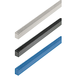
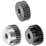
Rack gears / contact angle 20 degrees / dimension L configurable (Part Numbers - CAD Download)
(i)Remark
- Please check the content on our website as the PDF does not contain the most up-to-date information.
Part Number
Once your search is narrowed to one product,
the corresponding part number is displayed here.
- Drawing / Specifications
- 3D Preview 3D preview is available after complete configuration
- Part Numbers
- Catalog
Dimensional Drawing
| ■ Hole Position Configurable Type (Number of Holes is up to 4) | ■ Number of Holes Configurable Type | |||||||||||||||||||||||||||||||||||||||||||||||||||||||||||||||||||||||||||||||||||||||||||||||||||
| |  |  | ||||||||||||||||||||||||||||||||||||||||||||||||||||||||||||||||||||||||||||||||||||||||||||||||||
Enlarged View of End Face
| ||||||||||||||||||||||||||||||||||||||||||||||||||||||||||||||||||||||||||||||||||||||||||||||||||||
| [ ! ] Up to four holes can be specified. [ ! ]A+B+C+D ≤ L-5 | [ ! ] F = L-B× (K-1)2 ≥ 15 | |||||||||||||||||||||||||||||||||||||||||||||||||||||||||||||||||||||||||||||||||||||||||||||||||||
| Metal: L Tolerance (mm) | Plastic: L Tolerance (mm) | W, H Dimension Tolerance (mm) | Accumulated Pitch Error (μm) | |||||||||||||||||||||||||||||||||||||||||||||||||||||||||||||||||||
|
|
|
| |||||||||||||||||||||||||||||||||||||||||||||||||||||||||||||||||||
| Type | [M] Material | [S] Surface Treatment | |
| Hole Position Configurable Type | Number of Holes Configurable Type | ||
| RGEAL | LRGEA | EN 1.1191 Equiv. | Black Oxide |
| RGEABL | LRGEAB | Free-cutting brass | - |
| RGEASL | LRGEAS | EN 1.4301 Equiv. | - |
| RGEAML | LRGEAM | MC Nylon (Blue) | - |
| RGEAPL | LRGEAP | Polyacetal (White) | - |
[!] Material: MC Nylon and Polyacetal dimensions may change depending on the operating environment.
[!] Flatness (warpage) accuracy is L = 500 or less: 0.2, 501 or more: 0.3.
[!] This product is not hardened.
Specification Table
| Part Number | — | L (Overall Length) | — | Hole Position (First) | — | Hole Position (Second) | — | Hole Position (Third) |
| RGEAML1.0Z | — | 450 | — | A50 | — | B150 | — | C150 |
| Part Number | — | L (Overall Length) | — | K (Number of Holes) | — | B (Hole Pitch) |
| LRGEA2.0ST | — | 900 | — | K8 | — | B80 |
| Part Number | Overall Length | Hole Position | P (Pitch) | W | H | h | ||
| L | ABC | |||||||
| Type | Module | Hole Machining | Unit: mm | Unit: mm | ||||
| (EN 1.1191 Equiv.) RGEAL (EN 1.4301 Equiv.) RGEASL (Polyacetal) RGEAPL | 0.5 | N (No Hole Machining) KA (Side Through Hole) | 20 to 480 | 5 to 475 | 1.571 | 3 | 9 | 8.5 |
| 0.8 | 2.513 | 4 | 10 | 9.2 | ||||
| 1.0 | N (No Hole Machining) HT (Back Tapped) ST (Side Tapped) Z (Side Counterbored) | 20 to 980 | 5 to 975 | 3.142 | 10 | 12 (10) | 11 (9) | |
| 1.5 | 4.712 | 15 | 20 (15) | 18.5 (13.5) | ||||
| 2.0 | 6.283 | 20 | 25 (20) | 23 (18) | ||||
| 2.5 | 7.854 | 25 | 30 (25) | 27.5 (22.5) | ||||
| 3.0 | 9.425 | 30 | 35 (30) | 32 (27) | ||||
| (Free-Cutting Brass) RGEABL (MC Nylon) RGEAML | 0.5 | N (No Hole Machining) KA (Side Through Hole) | 20 to 280 | 5 to 275 | 1.571 | 3 | 9 | 8.5 |
| 0.8 | 2.513 | 4 | 10 | 9.2 | ||||
| 1.0 | N,HT,ST,Z | 20 to 480 | 5 to 475 | 3.142 | 10 | 12 | 11 | |
| Part Number | Overall Length | K | B | P (Pitch) | W | H | h | ||
| L | (Number of Holes) | (Hole Pitch) | |||||||
| Type | Module | Hole Machining | Unit: mm | Unit: mm | |||||
| (EN 1.1191 Equiv.) LRGEA (EN 1.4301 Equiv.) LRGEAS (Polyacetal) LRGEAP | 0.5 | N (No Hole Machining) KA (Side Through Hole) | 20 to 480 | 2 to 8 | 50 to 450 | 1.571 | 3 | 9 | 8.5 |
| 0.8 | 2.513 | 4 | 10 | 9.2 | |||||
| 1.0 | N (No Hole Machining) HT (Back Tapped) ST (Side Tapped) Z (Side Counterbored) | 20 to 980 | 2 to 12 | 50 to 500 | 3.142 | 10 | 12 (10) | 11 (9) | |
| 1.5 | 4.712 | 15 | 20 (15) | 18.5 (13.5) | |||||
| 2.0 | 6.283 | 20 | 25 (20) | 23 (18) | |||||
| 2.5 | 7.854 | 25 | 30 (25) | 27.5 (22.5) | |||||
| 3.0 | 9.425 | 30 | 35 (30) | 32 (27) | |||||
| (Free-Cutting Brass) LRGEAB (MC Nylon) LRGEAM | 0.5 | N (No Hole Machining) KA (Side Through Hole) | 20 to 280 | 2 to 5 | 50 to 280 | 1.571 | 3 | 9 | 8.5 |
| 0.8 | 2.513 | 4 | 10 | 9.2 | |||||
| 1.0 | N,HT,ST,Z | 20 to 480 | 2 to 8 | 50 to 480 | 3.142 | 10 | 12 | 11 | |
Alterations
| Alterations | One End Tapped | Both Ends Tapped | Tapped Hole Dimension Change | ||||||||||||||||||||||||||||||
| Code | MC | WMC | TPC | ||||||||||||||||||||||||||||||
| Spec. | Ordering Code MC5 | Ordering Code WMC5 | Changes the tapped hole dimension. Ordering Code TPC4
| ||||||||||||||||||||||||||||||
 |
|  |
| ||||||||||||||||||||||||||||||
| [NG] For RGEAS, M4 is not available for module 1.0. | [NG] For RGEAS, M4 is not available for module 1.0. | ||||||||||||||||||||||||||||||||
General information - Rack Gears

Selection Details of Rack Gears
-Material: steel, stainless steel, brass, plastic
-Coatings: uncoated, burnished
-Heat treatment: untreated, surface curing (induction hardened)
-Module: 0.5, 0.8, 1, 1.5, 2, 2.5, 3
-Width: 3 to 30 mm
-Number of teeth: 9 to 192
-Outer diameter (round): 8 to 30 mm
-Length: 20 to 1980 mm
Description / Rack Gear Basics
The rack gear from MISUMI are fundamentally used for motion conversion. The rack gear allows converting a rotary motion into a linear motion or a linear motion into a rotary motion. A rack gear can transmit high forces due to the form-fitting gearing. In connection with a gear wheel or spur gear, a gear rack drive forms a slip-free transmission of force and prevents a slip-through. For a large number of applications, the slip-free transmission of the rack gear is an efficient transmission of force and motion. The rack gear drive also withstands high loads with a compact design. With rack gears, high speeds can also be driven in applications with low noise generation. With MISUMI, you can configure your rack gears individually in length and in other parameters.
During the transfer of motion, the teeth intertwine and largely unroll during the transfer to one another. The rack gear can be used for the transfer of motion almost over the entire length. To prevent the gear wheel from overflowing, for example, stopper bolts or stopper blocks are recommended. Since the module is standardized, it must be ensured for the construction of a rack drive that the same module is used for the rack and the gear wheel. The rack gear allows precise control by directly transmitting motion, torque and speed.
For high wear resistance and reliability, our product range also offers surface-hardened rack gears. The hardened rack gear has a harder surface of the teeth, which makes it less susceptible to wear and tear. Their long service life helps reduce production downtime. Hardened rack gears are also less susceptible to locking-related play and retain their precision in the long term. This aspect makes hardened rack gears particularly recommended for precise applications.
A rack gear drive has a low backlash. In general, the tooth flank clearance is used for assembly and thermal expansion. Like the head play, it can serve as a gap for lubricants. For very precise applications, the reverse play is not beneficial. In order to minimize this during precision applications, pre-tensioning is required. On lifting tables, the dead weight already generates a vertical pretension in the rack gear, which minimizes the reverse play. If the rack gear is aligned horizontally, a separate pretension should be used to reduce the reverse play. This can be achieved with tension springs or other exciting components, for example. When selecting a suitable rack gear, the first decision criterion is the material of the rack gear drive. The following are some advantages of the rack gear materials:
Steel rack gears
Rack gears made of steel have high strength and withstand high loads. Therefore, steel rack gears are suitable for heavy loads. The material surface can be hardened to increase wear resistance. This makes the rack gear resistant and durable. In addition, steel is very heat-resistant and is suitable for applications in which high ambient temperatures occur. One disadvantage of steel is its low corrosion resistance.
Stainless steel rack gears
Stainless steel rack gears are highly corrosion resistant, since stainless steel forms a passive layer (oxide layer). This makes them suitable for applications where higher humidity is found. Furthermore, stainless steel offers good chemical resistance. Like steel, stainless steel is temperature resistant without losing strength. High temperatures can cause discoloration (tempering colour) in stainless steel. However, this does not affect the function in any way. Similar to the steel, stainless steel is robust and has a long service life. Another advantage is that rack gears made of stainless steel have hygienic properties. Therefore, this material is often used in the pharmaceutical industry and in medical technology.
Brass rack gears
Brass rack gears are well protected against corrosion. Therefore, a brass rack gear is well suited in corrosive environments. Depending on the application, it can be advantageous that brass does not tend to spark when abrasion is applied. In addition, brass has a high strength and ductility. This allows the material to deform before it breaks. Brass rack gears have a high thermal conductivity, which allows heat to be dissipated similar to a heat sink. The perhaps most important property of the brass rack gear is its gliding property. In the case of a lubrication film dissipates, this property serves as a certain fail-safe.
Lubrication of rack gears
The lubrication of the rack gear is decisive for low-wear operation. The lubrication reduces the friction on the tooth flanks of the rack gear and the pinion, which reduces the material abrasion. In this way, proper lubrication of the rack gear increases the service life, performance and ensures long-term precision. In principle, a rack can be lubricated with grease or oil. The type of lubrication that is suitable depends on several factors such as temperature, load and speed. Grease lubrication is often used for high loads and torques, while oil lubrication is used for high speeds. Lubricant manufacturers offer a suitable lubricant for almost all load cases. Before re-lubricating, the tooth drive should be thoroughly cleaned to prevent damage to the tooth flanks or teeth from contamination. Depending on the application, the lubricant can be sprayed, brushed, or sprayed onto the rack gear. The lubrication intervals must be selected depending on the application and the lubricant used. It is always recommended to adjust the lubrication intervals to the given circumstances.
Application Examples - Rack Gears
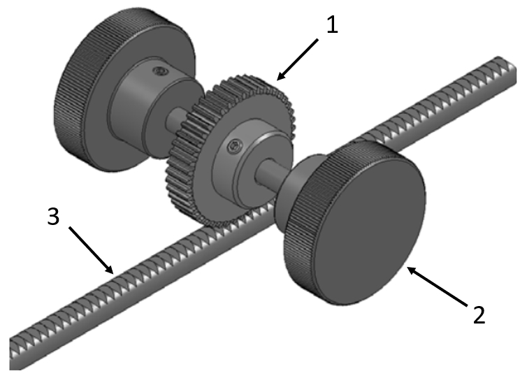
Application example - rack gear with spur gear
(1) Spur gear, (2) Clamping knobs, (3) Rack gear
Industrial Applications




Part Number:
- In order to open the 3D preview, the part number must be fixed.
3D preview is not available, because the part number has not yet been determined.
| Part Number | Minimum order quantity | Volume Discount | RoHS | Characteristics/Applications | Module | Length L (mm) | Material | Material Details | Surface Treatment | Tooth Width W (or D) (mm) | Rack Height (mm) | Hole Machining | Hole Position [B] / Hole Pitch [B] (mm) | Hole Position (First) [A] (mm) | K | |
|---|---|---|---|---|---|---|---|---|---|---|---|---|---|---|---|---|
| 1 | 7 Days | - | Non-magnetic | 0.5 | 20 ~ 280 | [Brass] Free-Cutting Brass Rod | Free-Cutting Brass | Not Provided | 3 | 9 | KA (Side Through Hole) | 50 ~ 280 | - | 2 ~ 5 | ||
| 1 | 7 Days | - | Non-magnetic | 0.5 | 20 ~ 280 | [Brass] Free-Cutting Brass Rod | Free-Cutting Brass | Not Provided | 3 | 9 | N (No Hole Machining) | - | - | - | ||
| 1 | 7 Days | - | Non-magnetic | 0.8 | 20 ~ 280 | [Brass] Free-Cutting Brass Rod | Free-Cutting Brass | Not Provided | 4 | 10 | KA (Side Through Hole) | 50 ~ 280 | - | 2 ~ 5 | ||
| 1 | 7 Days | - | Non-magnetic | 0.8 | 20 ~ 280 | [Brass] Free-Cutting Brass Rod | Free-Cutting Brass | Not Provided | 4 | 10 | N (No Hole Machining) | - | - | - | ||
| 1 | 7 Days | - | Non-magnetic | 1 | 20 ~ 480 | [Brass] Free-Cutting Brass Rod | Free-Cutting Brass | Not Provided | 10 | 12 | HT (Back Tapped) | 50 ~ 450 | - | 2 ~ 8 | ||
| 1 | 7 Days | - | Non-magnetic | 1 | 20 ~ 480 | [Brass] Free-Cutting Brass Rod | Free-Cutting Brass | Not Provided | 10 | 12 | N (No Hole Machining) | - | - | - | ||
| 1 | 7 Days | - | Non-magnetic | 1 | 20 ~ 480 | [Brass] Free-Cutting Brass Rod | Free-Cutting Brass | Not Provided | 10 | 12 | ST (Side Tapped) | 50 ~ 450 | - | 2 ~ 8 | ||
| 1 | 7 Days | - | Non-magnetic | 1 | 20 ~ 480 | [Brass] Free-Cutting Brass Rod | Free-Cutting Brass | Not Provided | 10 | 12 | Z (Side Counterbored) | 50 ~ 450 | - | 2 ~ 8 | ||
| 1 | 7 Days | - | Non-magnetic | 0.5 | 20 ~ 280 | [Brass] Free-Cutting Brass Rod | Free-Cutting Brass | Not Provided | 3 | 9 | KA (Side Through Hole) | - | 5 ~ 275 | - | ||
| 1 | 7 Days | 10 | Non-magnetic | 0.5 | 20 ~ 280 | [Brass] Free-Cutting Brass Rod | Free-Cutting Brass | Not Provided | 3 | 9 | N (No Hole Machining) | - | - | - | ||
| 1 | 7 Days | - | Non-magnetic | 0.8 | 20 ~ 280 | [Brass] Free-Cutting Brass Rod | Free-Cutting Brass | Not Provided | 4 | 10 | KA (Side Through Hole) | - | 5 ~ 275 | - | ||
| 1 | 7 Days | 10 | Non-magnetic | 0.8 | 20 ~ 280 | [Brass] Free-Cutting Brass Rod | Free-Cutting Brass | Not Provided | 4 | 10 | N (No Hole Machining) | - | - | - | ||
| 1 | 7 Days | - | Non-magnetic | 1 | 20 ~ 480 | [Brass] Free-Cutting Brass Rod | Free-Cutting Brass | Not Provided | 10 | 12 | HT (Back Tapped) | - | 5 ~ 475 | - | ||
| 1 | 7 Days | - | Non-magnetic | 1 | 20 ~ 480 | [Brass] Free-Cutting Brass Rod | Free-Cutting Brass | Not Provided | 10 | 12 | N (No Hole Machining) | - | - | - | ||
| 1 | 7 Days | - | Non-magnetic | 1 | 20 ~ 480 | [Brass] Free-Cutting Brass Rod | Free-Cutting Brass | Not Provided | 10 | 12 | ST (Side Tapped) | - | 5 ~ 475 | - | ||
| 1 | 7 Days | - | Non-magnetic | 1 | 20 ~ 480 | [Brass] Free-Cutting Brass Rod | Free-Cutting Brass | Not Provided | 10 | 12 | Z (Side Counterbored) | - | 5 ~ 475 | - |
Loading...
Basic information
| Tooth Type | Standard | Environmentally friendly | RoHS Compliant (10 Substances) | Shape | Rack Gears |
|---|---|---|---|---|---|
| Heat Treatment | Not Provided | Ground Tooth | Not Provided | End Face Machining | One End Machined |
Configure
Basic Attributes
-
Characteristics/Applications
-
Module
-
Length L(mm)
-
Material
- General Steel Material
- Stainless Steel
- Resin
- Brass
- General Steel Material
-
Surface Treatment
- Not Provided
- Black Oxide
-
Tooth Width W (or D)(mm)
-
Hole Machining
- HT (Back Tapped)
- KA (Side Through Hole)
- N (No Hole Machining)
- ST (Side Tapped)
- Z (Side Counterbored)
-
Hole Position [B] / Hole Pitch [B](mm)
-
Hole Position (First) [A](mm)
-
K
-
Type
- LRGEA
- LRGEAB
- LRGEAM
- LRGEAP
- LRGEAS
- RGEABL
- RGEAL
- RGEAML
- RGEAPL
- RGEASL
-
Material Details
- EN 1.1191 Equiv.
- EN 1.4301 Equiv.
- Free-Cutting Brass
- MC Nylon
- Polyacetal
-
Filter by CAD data type
- 2D
- 3D
Filter by standard shipping days
-
- All
- 7 Days or Less
Optional Attributes
- The specifications and dimensions of some parts may not be fully covered. For exact details, refer to manufacturer catalogs .
Frequently Asked Questions (FAQ)
-
Question:
What are rack gears for?
-
Answer:
Rack gears are machine elements that convert rotary motion into linear motion. This can also be done in reverse order. The rack gear can transmit high forces directly and without slip with a gear wheel.
-
Question:
What materials are used for rack gears?
-
Answer:
MISUMI’s rack gears are made of steel, stainless steel (stainless steel), brass and plastic. Each material offers different properties that must be selected to suit a wide range of requirements.
-
Question:
What types of rack gears do you offer?
-
Answer:
There are straight-toothed rack gears and slanted rack gears. The rack gears with straight gearing are often used to implement linear motion. The obliquely toothed rack gears are often used for conversion into a rotation.
-
Question:
How are rack gears lubricated?
-
Answer:
In most cases, a rack gear is lubricated with grease or oil. The appropriate lubricant should be used depending on the application (heavy loads, high temperature, high speed). For high-speed applications, oil is usually used. A grease is often used in heavy load applications.
-
Question:
What are the advantages of rack gears?
-
Answer:
Rack gears withstand high loads and have a long service life. At the same time, rack gears are very precise and easy to assemble.
Complementary Products
MISUMI Unit еxample related to this product
Tech Support
- Technical Support
- Tel:+49 69 668173-0 / FAX:+49 69 668173-360
- Technical Inquiry
