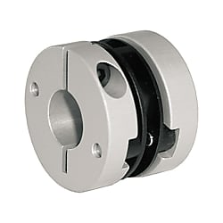
Servo couplings / hub clamping / 1 disc: PI / body: aluminium / FSKK / ABP Antriebstechnik
- Promotional pricing ends 30/11/2024
- Volume Discount
Part Number
Once your search is narrowed to one product,
the corresponding part number is displayed here.
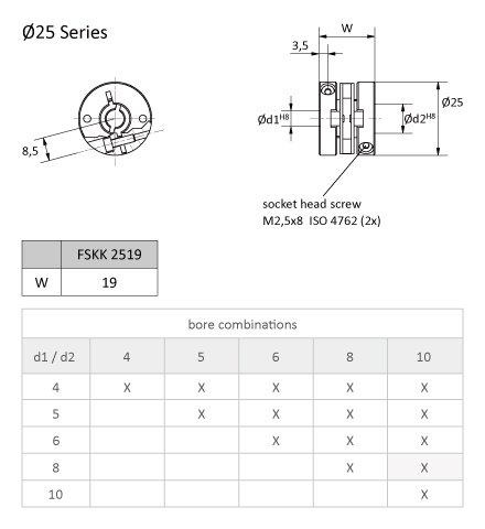
FSKK 2519
Part No. Example: FSKK 2519 08/10
(Series ØW d1/d2)
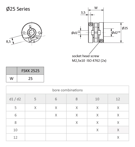
FSKK 2525
Part No. Example: FSKK 2525 10/12
(Series ØW d1/d2)
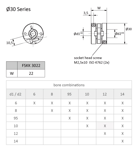
FSKK 3022
Part No. Example: FSKK 3022 10/12
(Series ØW d1/d2)
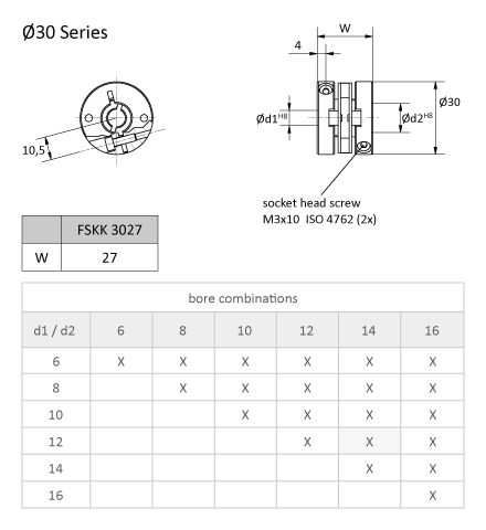
FSKK 3027
Part No. Example: FSKK 3027 12/14
(Series ØW d1/d2)
Part Number
|
|---|
| FSKK 2525 08/08 |
| FSKK 2525 10/10 |
| FSKK 3022 95/95 |
| FSKK 3027 06/06 |
| FSKK 3027 08/10 |
| FSKK 3027 08/12 |
| FSKK 3027 08/16 |
| Part Number |
Standard Unit Price
| Minimum order quantity | Volume Discount | Shaft Bore Dia. (machined) D1 (mm) | Shaft Bore Dia. (machined) D2 (mm) | Outer Dia. A (mm) | Overall Length W (mm) | Allowable Torque (Nm) | Allowable Lateral Misalignment (mm) | Allowable Angular Misalignment (deg) | Allowable Axial Clearance (±) (mm) | Moment of Inertia (g・cm2) | |
|---|---|---|---|---|---|---|---|---|---|---|---|---|---|
41.75 € | 1 | Available | 3 Days | 8 | 8 | 25 | 25 | 0.65 | ±0.3 | ±2.5 | 0.4 | 2.1 | |
41.75 € | 1 | Available | 3 Days | 10 | 10 | 25 | 25 | 0.65 | ±0.3 | ±2.5 | 0.4 | 2.9 | |
43.75 € | 1 | Available | 3 Days | 9.52 | 9.52 | 30 | 22 | 1.2 | ±0.3 | ±2.5 | 0.4 | 2.1 | |
43.75 € | 1 | Available | 3 Days | 6 | 6 | 30 | 27 | 1.2 | ±0.3 | ±2.5 | 0.4 | 2.8 | |
43.75 € | 1 | Available | 3 Days | 8 | 10 | 30 | 27 | 1.2 | ±0.3 | ±2.5 | 0.4 | 37 | |
43.75 € | 1 | Available | 3 Days | 8 | 12 | 30 | 27 | 1.2 | ±0.3 | ±2.5 | 0.2 | 2.5 | |
43.75 € | 1 | Available | 3 Days | 8 | 16 | 30 | 27 | 1.2 | ±0.3 | ±2.5 | 0.4 | 22.2 |
Loading...
Technical Information
| Technical data | FSKK 2519 | FSKK 2525 | FSKK 3022 | FSKK 3027 | |
|---|---|---|---|---|---|
| Max. speed | min-1 | 12.000 | 12.000 | 12.000 | 12.000 |
| Max. torque | Ncm | 40 | 40 | 60 | 60 |
| Max. offset off shafts | |||||
| Radial | mm | ± 0,25 | ± 0,25 | ± 0,3 | ± 0,3 |
| Axial | mm | ± 0,4 | ± 0,4 | ± 0,4 | ± 0,4 |
| Angular | Grad | ± 2,5 | ± 2,5 | ± 2,5 | ± 2,5 |
| Torsion spring stiffness | Nm/rad | 22 | 22 | 30 | 30 |
| Radial spring stiffness | N/mm | 60 | 60 | 40 | 40 |
| Moment of inertia | gcm2 | 13,5 | 15 | 35 | 37 |
| Max. clamping torque (M) | Ncm | 65 | 65 | 120 | 120 |
| Temperature range | °C | -10 to +80 | |||
| Weight appr. | g | 16 | 18 | 30 | 32 |
| Material | Flange | Aluminium, anodised | |||
| Material | Membrane | Polyamid 6.6, fiberglas reinforced | |||
M = tightening torque of the clamping screw
Because of the material properties of plastic, a dimensional deviation of up to 0.5 mm can occur in the length.
Basic information
| Type | Disc Type | Allowable Misalignment | Angular Misalignment / Eccentricity / Axial Misalignment | Application | Standard / Servo Motor / Stepping Motor / Encoder |
|---|---|---|---|---|---|
| Allowable Torque Range(N•m) | 0.05 to 1.00 | Max. Rotational Speed Range(r/min) | 10,001 to 78,000 | Feature | High Durability / Low Moment of Inertia / Vibration Insulation / Small / Clean Environment |
| Body Material | Aluminum | Max. Rotational Speed(r/min) | 12000 | Allowable Lateral Misalignment Range(mm) | 0.21 to 0.40 |
| Disc Part Material | Polyimide | Operating Temperature Range(°C) | -10::80 |
Configure
Basic Attributes
-
Shaft Bore Dia. (machined) D1(mm)
-
Shaft Bore Dia. (machined) D2(mm)
-
Outer Dia. A(mm)
-
Overall Length W(mm)
-
Allowable Torque(Nm)
-
Allowable Lateral Misalignment(mm)
-
Moment of Inertia(g・cm2)
-
Type
- FSKK 2519
- FSKK 2525
- FSKK 3022
- FSKK 3027
-
Allowable Angular Misalignment(deg)
-
Filter by CAD data type
- 3D
Filter by standard shipping days
-
- All
- Same day
- 3 Days or Less
Optional Attributes
- The specifications and dimensions of some parts may not be fully covered. For exact details, refer to manufacturer catalogs .
