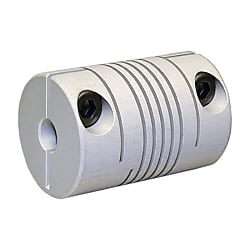
Helical slit couplings / body: aluminium, stainless steel / WKAK, WKAS, WKAS, WKXK, WKXS / ABP Antriebstechnik
- Promotional pricing ends 30/11/2024
- Volume Discount
Part Number
Once your search is narrowed to one product,
the corresponding part number is displayed here.
Contents
- WKAK Ø12 / Ø14 / Ø16 / Ø19 / Ø25 / Ø30 Series
- WKAS Ø6,5 / Ø10 / Ø12 / Ø16 / Ø19 / Ø20 Series
- WKAS Ø25 / Ø30 Series
- WKXK Ø25 Series, WKXS Ø25 Series
WKAK Ø12 / Ø14 / Ø16 / Ø19 / Ø25 / Ø30 Series
Technical Information
| Technical data | WKAK 1215 | WKAK 1421 | WKAK 1625 | WKAK 1928 | WKAK 2532 | WKAK 3038 | |
|---|---|---|---|---|---|---|---|
| Max. speed | min-1 | 8.000 | 6.000 | 6.000 | 6.000 | 6.000 | 6.000 |
| Max. torque | Ncm | 25 | 50 | 60 | 80 | 100 | 150 |
| Max. offset off shafts | |||||||
| Radial | mm | ± 0,15 | ± 0,2 | ± 0,2 | ± 0,25 | ± 0,35 | ± 0,35 |
| Axial | mm | ± 0,2 | ± 0,25 | ± 0,3 | ± 0,4 | ± 0,5 | ± 0,5 |
| Angular | Grad | ± 2 | ± 3 | ± 3,5 | ± 4 | ± 4 | ± 4 |
| Torsion spring stiffness | Nm/rad | 2,5 | 4,5 | 5,5 | 8 | 16 | 19 |
| Radial spring stiffness | N/mm | 55 | 22 | 30 | 36 | 45 | 60 |
| Moment of inertia | gcm2 | 1 | 1,9 | 3,8 | 8,7 | 29 | 76 |
| Max. clamping torque (M) | Ncm | 30 | 50 | 50 | 120 | 150 | 150 |
| Temperature range | °C | -30 to +150 | -30 to +120 | -30 to +150 | |||
| Weight appr. | g | 3,5 | 6,5 | 10 | 16 | 34 | 58 |
| Material | Flange | Aluminium | Aluminium anodised | ||||
M = tightening torque of the clamping screw
Drawings and Bore Combinations
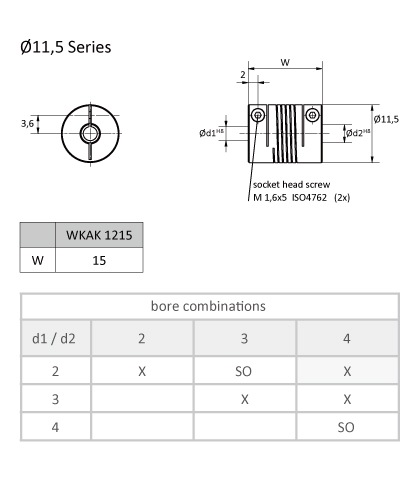
Part No. Example: WKAK 1215 02/04
(Series ØW d1/d2)
SO = special bores at extra charge
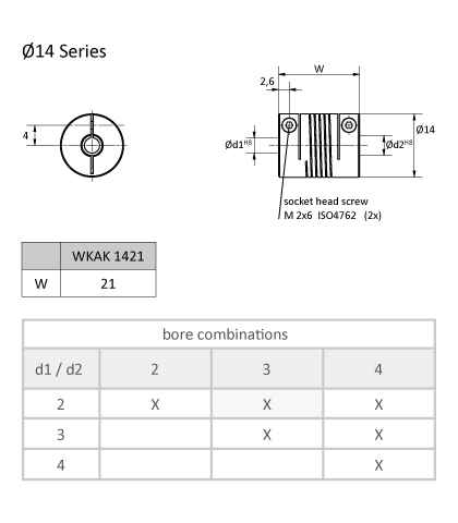
Part No. Example: WKAK 1421 02/03
(Series ØW d1/d2)
SO = special bores at extra charge
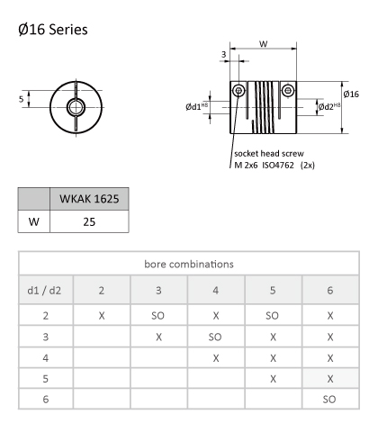
Part No. Example: WKAK 1625 05/06
(Series ØW d1/d2)
SO = special bores at extra charge
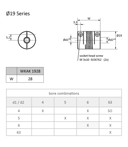
Part No. Example: WKAK 1928 06/06
(Series ØW d1/d2)
SO = special bores at extra charge
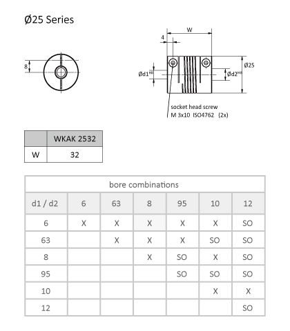
Part No. Example: WKAK 2532 06/08
(Series ØW d1/d2)
SO = special bores at extra charge
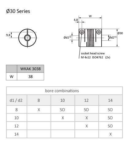
Part No. Example: WKAK 3038 10/12
(Series ØW d1/d2)
SO = special bores at extra charge
WKAS Ø6,5 / Ø10 / Ø12 / Ø16 / Ø19 / Ø20 Series
Technical Information
| Technical data | WKAS 6508 | WKAS 1015 | WKAS 1218 | WKAS 1622 | WKAS 1922 | WKAS 2019 | |
|---|---|---|---|---|---|---|---|
| Max. speed | min-1 | 8.000 | 8.000 | 8.000 | 8.000 | 8.000 | 8.000 |
| Max. torque | Ncm | 2 | 15 | 25 | 40 | 60 | 60 |
| Max. offset off shafts | |||||||
| Radial | mm | ± 0,1 | ± 0,15 | ± 0,15 | ± 0,2 | ± 0,25 | ± 0,25 |
| Axial | mm | ± 0,15 | ± 0,2 | ± 0,25 | ± 0,3 | ± 0,4 | ± 0,4 |
| Angular | Grad | ± 2 | ± 2 | ± 2,5 | ± 3 | ± 3,5 | ± 3,5 |
| Torsion spring stiffness | Nm/rad | 0,55 | 2,2 | 2,8 | 5 | 9 | 9 |
| Radial spring stiffness | N/mm | 24 | 22 | 28 | 34 | 40 | 40 |
| Moment of inertia | gcm2 | 0,02 | 0,34 | 0,83 | 3,2 | 6,7 | 6 |
| Max. clamping torque (M) | Ncm | 8 | 15 | 35 | 80 | 80 | 80 |
| Temperature range | °C | -30 to +150 | |||||
| Weight appr. | g | 0,5 | 2,4 | 4 | 9,5 | 13 | 12 |
| Material | Flange | Aluminium, anodised | Aluminium | ||||
M = tightening torque of the clamping screw
Helix area free turned from Ø 5 mm
Drawings and Bore Combinations
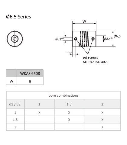
Part No. Example: WKAS 6508 1,5/02
(Series ØW d1/d2)
SO = special bores at extra charge
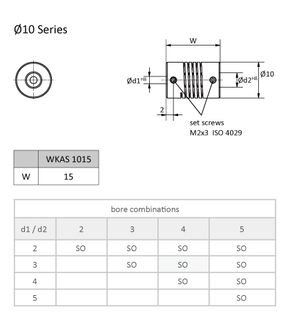
Part No. Example: WKAS 1015 03/04
(Series ØW d1/d2)
SO = special bores at extra charge
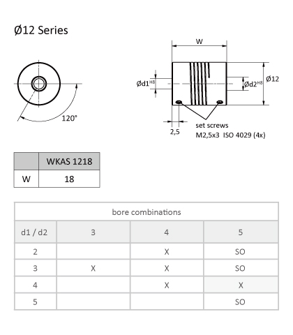
Part No. Example: WKAS 1218 04/05
(Series ØW d1/d2)
SO = special bores at extra charge
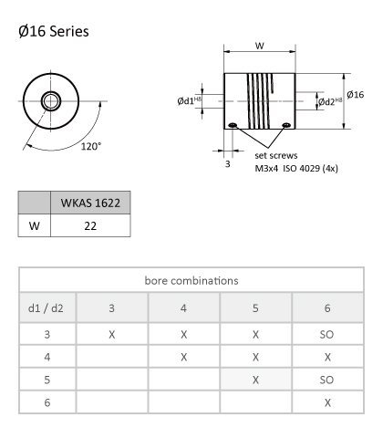
Part No. Example: WKAS 1622 05/05
(Series ØW d1/d2)
SO = special bores at extra charge
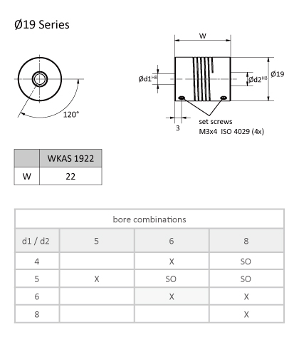
Part No. Example: WKAS 1922 06/06
(Series ØW d1/d2)
SO = special bores at extra charge
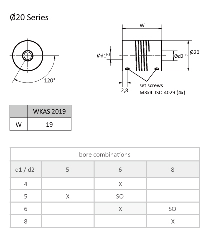
Part No. Example: WKAS 2019 06/06
(Series ØW d1/d2)
SO = special bores at extra charge
WKAS Ø25 / Ø30 Series
Technical Information
| Technical data | WKAS 2524 | WKAS 2532 | WKAS 3030 | WKAS 3038 | |
|---|---|---|---|---|---|
| Max. speed | min-1 | 8.000 | 8.000 | 8.000 | 8.000 |
| Max. torque | Ncm | 100 | 100 | 150 | 150 |
| Max. offset off shafts | |||||
| Radial | mm | ± 0,3 | ± 0,3 | ± 0,3 | ± 0,3 |
| Axial | mm | ± 0,5 | ± 0,5 | ± 0,5 | ± 0,5 |
| Angular | Grad | ± 4 | ± 4 | ± 4 | ± 4 |
| Torsion spring stiffness | Nm/rad | 20 | 18 | 21 | 21 |
| Radial spring stiffness | N/mm | 60 | 50 | 60 | 60 |
| Moment of inertia | gcm2 | 22,2 | 30 | 57 | 76 |
| Max. clamping torque (M) | Ncm | 120 | 120 | 120 | 120 |
| Temperature range | °C | -30 to +150 | |||
| Weight appr. | g | 26 | 35 | 45 | 60 |
| Material | Flange | Aluminium anodised | |||
M = tightening torque of the clamping screw
Helix area free-turned
Drawings and Bore Combinations
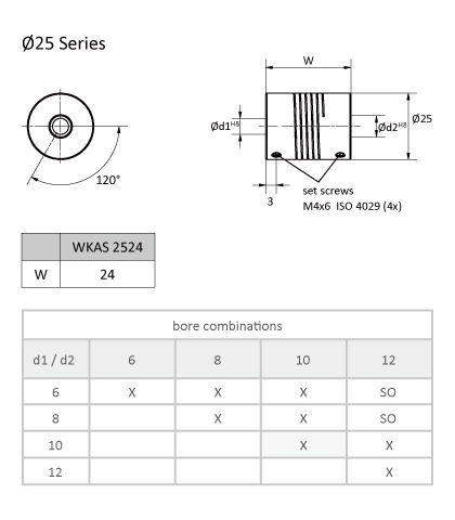
WKAS 2524
Part No. Example: WKAS 2524 10/10
(Series ØW d1/d2)
SO = special bores at extra charge
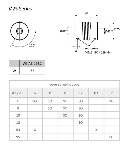
WKAS 2532
Part No. Example: WKAS 2532 10/10
(Series ØW d1/d2)
SO = special bores at extra charge
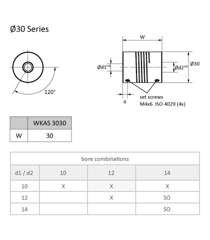
WKAS 3030
Part No. Example: WKAS 3030 10/12
(Series ØW d1/d2)
SO = special bores at extra charge
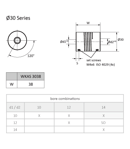
WKAS 3038
Part No. Example: WKAS 3038 10/14
(Series ØW d1/d2)
SO = special bores at extra charge
WKXK Ø25 Series, WKXS Ø25 Series
Technical Information
| Technical data | WKXK 2532 | WKXS 2524 | |
|---|---|---|---|
| Max. speed | min-1 | 6.000 | 8.000 |
| Max. torque | Ncm | 200 | 200 |
| Max. offset off shafts | |||
| Radial | mm | ± 0,35 | ± 0,3 |
| Axial | mm | ± 0,5 | ± 0,5 |
| Angular | Grad | ± 4 | ± 4 |
| Torsion spring stiffness | Nm/rad | 29 | 40 |
| Radial spring stiffness | N/mm | 150 | 250 |
| Moment of inertia | gcm2 | 84 | 64 |
| Max. clamping torque (M) | Ncm | 150 | 120 |
| Temperature range | °C | -30 to +180 | |
| Weight appr. | g | 88 | 65 |
| Material | Stainless steel 1.4104 | ||
M = tightening torque of the clamping screw
Helix area free-turned
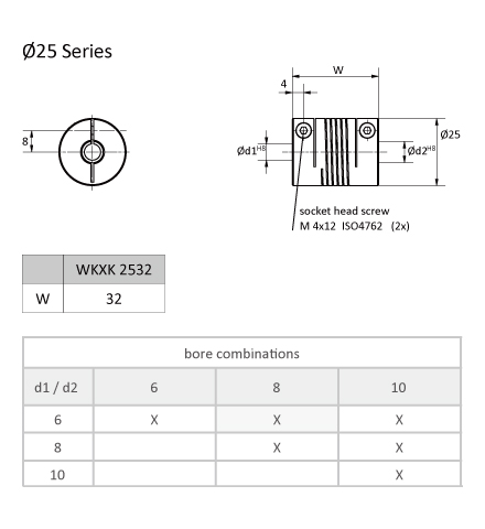
WKXK 2532
Part No. Example: WKXK 2532 06/08
(Series ØW d1/d2)
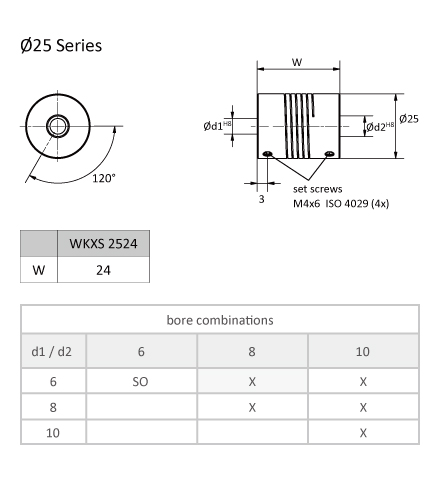
WKXS 2524
Part No. Example: WKXS 2524 06/08
(Series ØW d1/d2)
SO = special bores at extra charge
Part Number
|
|---|
| WKAK 1421 02/02 |
| WKAK 1625 03/03 |
| Part Number |
Standard Unit Price
| Minimum order quantity | Volume Discount | Allowable Torque Range (N•m) | Shaft Bore Dia. (machined) D1 (mm) | Shaft Bore Dia. (machined) D2 (mm) | Outer Dia. A (mm) | Overall Length W (mm) | Feature | Body Material | Allowable Torque (Nm) | Max. Rotational Speed (r/min) | Allowable Lateral Misalignment Range (mm) | Allowable Lateral Misalignment (mm) | Allowable Angular Misalignment (deg) | Operating Temperature Range (°C) | Allowable Axial Clearance (±) (mm) | Moment of Inertia (g・cm2) | |
|---|---|---|---|---|---|---|---|---|---|---|---|---|---|---|---|---|---|---|---|
41.95 € | 1 | Available | 3 Days | 0.05 to 1.00 | 2 | 2 | 14 | 21 | High Accuracy / High Durability / No Backlash / Low Moment of Inertia / Vibration Insulation / Small / Heat Resistant / Clean Environment | Aluminum | 0.5 | 6000 | 0.21 to 0.40 | ±2.5 | ±10 | -30~150 | 2.5 | 9.5 | |
41.95 € | 1 | Available | 3 Days | 0.05 to 1.00 | 3 | 3 | 16 | 25 | High Accuracy / High Durability / No Backlash / Low Moment of Inertia / Vibration Insulation / Heat Resistant / Clean Environment | Aluminum | 0.5 | 6000 | 0.21 to 0.40 | ±2.5 | ±10 | -30~150 | 2.5 | 3.8 |
Loading...
Basic information
| Type | With Slit | Allowable Misalignment | Angular Misalignment / Eccentricity / Axial Misalignment | Application | Standard / Servo Motor / Stepping Motor / Encoder |
|---|---|---|---|---|---|
| Max. Rotational Speed Range(r/min) | 4,001 to 10,000 |
Configure
Basic Attributes
-
Allowable Torque Range(N•m)
-
Shaft Bore Dia. (machined) D1(mm)
-
Shaft Bore Dia. (machined) D2(mm)
-
Outer Dia. A(mm)
-
Overall Length W(mm)
-
Feature
-
Body Material
-
Allowable Torque(Nm)
-
Max. Rotational Speed(r/min)
-
Allowable Lateral Misalignment Range(mm)
-
Allowable Lateral Misalignment(mm)
-
Moment of Inertia(g・cm2)
-
Type
- WKAK 1421
- WKAK 1625
- WKAK 1928
- WKAK 2532
- WKAK 3038
- WKAS 1015
- WKAS 1218
- WKAS 1622
- WKAS 1922
- WKAS 2524
- WKAS 2532
- WKAS 3030
- WKAS 3038
- WKXK 2532
- WKXS 2524
-
Allowable Angular Misalignment(deg)
-
Filter by CAD data type
- 3D
Filter by standard shipping days
-
- All
- Same day
- 3 Days or Less
- 4 Days or Less
- 5 Days or Less
Optional Attributes
- The specifications and dimensions of some parts may not be fully covered. For exact details, refer to manufacturer catalogs .
Tech Support
- Technical Support
- Tel:+49 69 668173-0 / FAX:+49 69 668173-360
- Technical Inquiry
