- inCAD Library Home
- > No.000276 Variable-angle conveyor
No.000276 Variable-angle conveyor
45
45
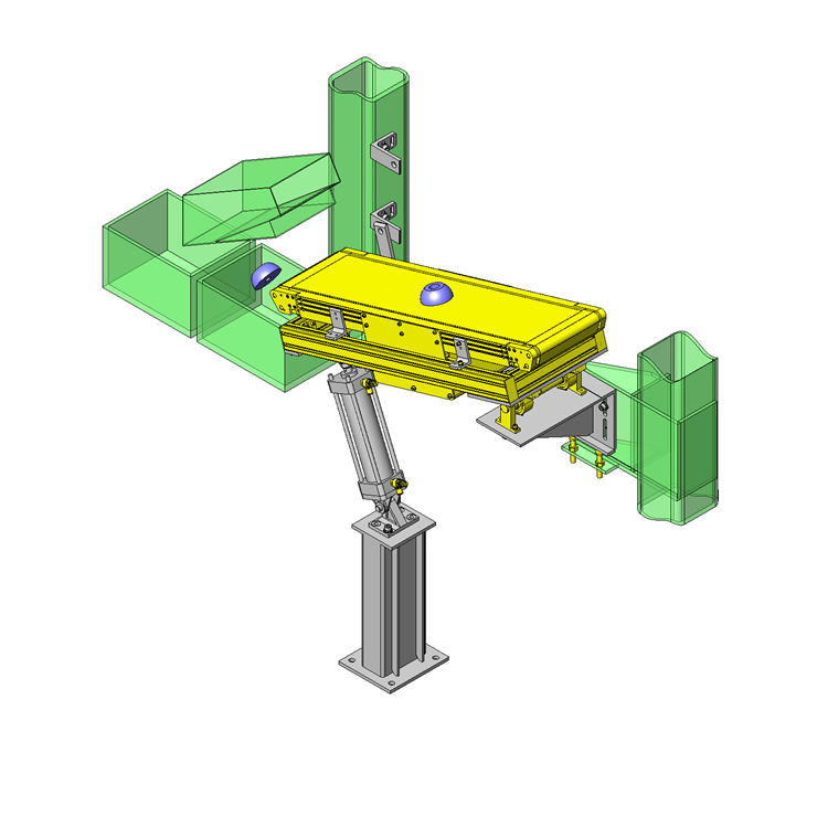
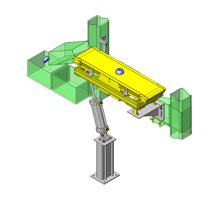
Using cylinder to change a slope of belt conveyor
Related Category
- * Unit assembly CAD data consists of some sub-assemblies.
Each sub-assembly unit can be used as it is or can be edited.
Application Overview
Purpose
- A conveyor that delivers two different type of workpieces into their respective container.
Points for use
- The cylinder, rotary shaft base and pin support are connected and placed on an external frame.
Target workpiece
- Plastic molded goods
- Dimensions: SR: 40mm x H: 32mm
- Mass: 0.16kg
Design Specifications
Operating Conditions or Design Requirements
- Drive part dimensions
- Height of bottom portion - conveyor at horizontal (maximum) position: 1242mm
- Conveyor length: 900mm, belt width: 200mm
- Frame width: 330mm
- Operation specifications
- Cylinder stroke: 200mm
- Difference of elevation at conveyor exit: 223.3mm
Selection Criteria for Main Components
- Cylinder capacity: 178N or more
Design Evaluation
Verification of main components
- Verify cylinder thrust for conveyor frame weight.
- Cylinder capacity:
- Conditional values: Distance between cylinder side hinge and rotary shaft: r1 = 715.5mm, Distance between frame center and rotary shaft: r2 = 325mm, conveyor frame part mass m = 40.0kg
- Thrust required for drive under moment around rotary shaft: F1 = F2 x r2/r1 Thus, F1 = 40 x 9.8 x 325/715.5 = 178N
- Operating air pressure: 0.5 MPa, cylinder I.D. 63mm, outstroke cylinder output at load factor of 0.5 F0 = 770N (SMC catalogue value)
- Safety factor: Sf = F0/F1 = 770/178 = 4.32
Other Design Consideration
- The workpiece guide is omitted because workpiece positioning is not necessary.
Explore Similar Application Examples
Page
-
/
-


