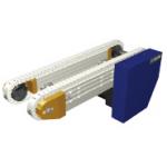
Miniature Conveyor
Product name | Miniature Conveyors - Plastic Chain |
Model number | CVSPA-200-1200-25-S200-IM-25-D-B |
Characteristic | Conveyor has a plastic chain for easy maintenance. |
* Orange colored cells in the table below indicate the part numbers that were actually used in this app. example.
Selection criteria
Dual belt track design.
Back to page top
Available sizes
■Miniature Conveyors - Plastic Chain, Dual Track, End Shaft Driven
| Material | Surface treatment |
Frame | Aluminum material | Anodize |
Motor cover | EN 1.0330 Equiv. | Paint |
Pulley holder | EN AW-5052 Equiv. | Gold anodize |
Plastic chain | Polyacetal | - |
■Basic specifications
Belt width | Distance between sprockets | Motor selection |
Output (W) | Voltage (V) | Specifications | Gearhead reduction ratio |
80 - 300 | 300 - 3000 | 25, 40 | * notes | 5, 7.5, 9, 12.5, 15, 18, 25, 30, 36, 50, 60, 75, 90, 100, 120, 150, 180 |
Back to page top
Performance info.
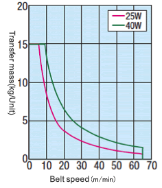
■Conveyor transfer capacity (Plastic chain conveyor)
Back to page top
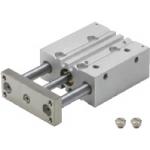
Cylinder with Twin Guides
Product name | Cylinders with Twin Guides |
Model number | MGCLF25-30 |
Characteristic | Cylinders with dual guide rods |
* Orange colored cells in the table below indicate the part numbers that were actually used in this app. example.
Selection criteria
Compact, guided cylinder design.
Back to page top
Available sizes
■Cylinders with Twin Guides
Tube I.D. | Bearing | Plain bearing | Linear bushing bearing | Cylinder width | Overall length (Value + St) | Thickness |
St | 10 | 20 | 25 | 30 | 40 | 50 | 75 | 100 | 10 | 20 | 25 | 30 | 40 | 50 | 75 | 100 |
O12 | ○ | ○ | - | ○ | ○ | ○ | ○ | ○ | ○ | ○ | - | ○ | ○ | ○ | ○ | ○ | 56 | 39 | 22 |
O16 | ○ | ○ | - | ○ | ○ | ○ | ○ | ○ | ○ | ○ | - | ○ | ○ | ○ | ○ | ○ | 62 | 43 | 25 |
O20 | - | ○ | - | ○ | ○ | ○ | ○ | ○ | - | ○ | - | ○ | ○ | ○ | ○ | ○ | 72 | 47 | 30 |
O25 | - | ○ | - | ○ | ○ | ○ | ○ | ○ | - | ○ | - | ○ | ○ | ○ | ○ | ○ | 86 | 47.5 | 38 |
O32 | - | - | ○ | - | - | ○ | ○ | ○ | - | - | ○ | - | - | ○ | ○ | ○ | 112 | 48 |
O50 | - | - | ○ | - | - | ○ | - | ○ | - | - | - | - | - | - | - | - | 146 | 72 | 60 |
* Sensor are sold separately
Back to page top
Accuracy Info
■Non-Rotational Accuracy of guided cylinder
Non-Rotational accuracy: Looseness by guide rod and bearing clearance represented in a rotation angle centered on the piston rod.
Tube I.D. | Non-rotating accuracy of tip link bar |
Plain bearing | Linear bushing |
O12 | ±0.12° | ±0.06° |
O16 | ±0.10° | ±0.06° |
O20 | ±0.09° | ±0.05° |
O25 | ±0.08° | ±0.05° |
O32 | ±0.06° | ±0.04° |
O50 | ±0.05° | - |
Back to page top
Performance info.
■Theoretical thrust
(N)
Tube I.D. | Operating direction | Operating pressure (MPa) |
0.4 | 0.5 |
O12 | Push | 45 | 57 |
Pull | 34 | 42 |
O16 | Push | 80 | 101 |
Pull | 60 | 75 |
O20 | Push | 126 | 157 |
Pull | 94 | 118 |
O25 | Push | 196 | 245 |
Pull | 151 | 189 |
O32 | Push | 322 | 402 |
Pull | 241 | 302 |
O50 | Push | 785 | 982 |
Pull | 660 | 825 |
■Allowable rotational torque
Shows the dynamic allowable value when rotational torque T is applied to the tips of the guide rod.
(N・m)
Tube I.D. | Bearing Type | Stroke |
10 | 20 | 25 | 30 | 40 | 50 | 75 | 100 |
O12 | Plain bearing | 0.50 | 0.40 | - | 0.33 | 0.28 | 0.25 | 0.77 | 0.65 |
Linear bushing | 0.41 | 0.31 | - | 0.25 | 0.69 | 0.59 | 0.40 | 0.32 |
O16 | Plain bearing | 0.91 | 0.75 | - | 0.64 | 0.56 | 0.49 | 1.25 | 1.06 |
Linear bushing | 0.76 | 0.60 | - | 0.49 | 1.14 | 1.02 | 0.79 | 0.65 |
O20 | Plain bearing | - | 1.43 | - | 1.23 | 1.08 | 0.96 | 1.51 | 1.27 |
Linear bushing | - | 1.12 | - | 0.93 | 2.12 | 1.90 | 1.50 | 1.24 |
O25 | Plain bearing | - | 2.26 | - | 1.94 | 1.71 | 1.52 | 2.38 | 2.00 |
Linear bushing | - | 1.98 | - | 1.65 | 3.75 | 3.37 | 2.68 | 2.22 |
O32 | Plain bearing | - | - | 6.71 | - | - | 5.24 | 4.30 | 3.64 |
Linear bushing | - | - | 3.61 | - | - | 2.55 | 6.48 | 5.41 |
O50 | Plain bearing | - | - | 13.0 | - | - | 10.8 | - | 10.6 |
■ Allowable lateral load
Shows the dynamic allowable value when lateral load W (perpendicular to guide rod) is applied to the tips of guide rod.
(N)
Tube I.D. | Bearing type | Stroke |
10 | 20 | 25 | 30 | 40 | 50 | 75 | 100 |
O12 | Plain bearing | 24 | 19 | - | 16 | 14 | 12 | 37 | 31 |
Linear bushing | 20 | 15 | - | 12 | 33 | 29 | 19 | 16 |
O16 | Plain bearing | 40 | 33 | - | 28 | 24 | 21 | 55 | 46 |
Linear bushing | 33 | 26 | - | 21 | 50 | 44 | 34 | 28 |
O20 | Plain bearing | - | 52 | - | 45 | 39 | 35 | 55 | 46 |
Linear bushing | - | 41 | - | 34 | 77 | 69 | 54 | 45 |
O25 | Plain bearing | - | 69 | - | 60 | 52 | 47 | 73 | 62 |
Linear bushing | - | 61 | - | 51 | 115 | 104 | 82 | 68 |
O32 | Plain bearing | - | - | 166 | - | - | 131 | 107 | 91 |
Linear bushing | - | - | 90 | - | - | 34 | 162 | 135 |
O50 | Plain bearing | - | - | 296 | - | - | 245 | - | 241 |
Back to page top
IDEA NOTE Position confirmation sensor
Since installing proximity sensors upward facing can cause detection errors, a mechanical switch is used.
IDEA NOTE Pallet guide
Use off-the-shelf items to reduce cost.