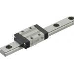
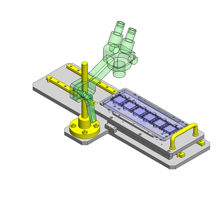
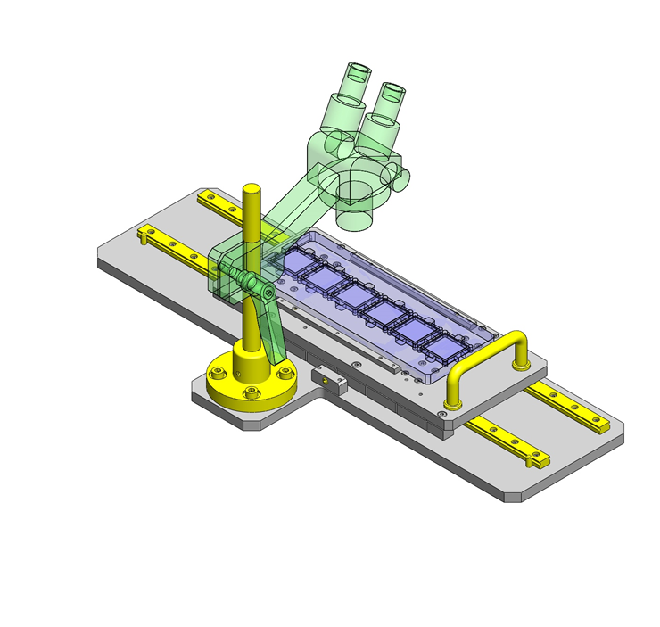
Miniature Linear Guide
| Product name | Miniature Linear Guides/Standard Blocks/Light Preload |
| Model number | SSE2B13-470 |
| Characteristic | The most basic type among all the industry standard-compliant blocks. |
* Orange colored cells in the table below indicate the part numbers that were actually used in this app. example.
Selection criteria
Linear guide is selected for accurate sliding.
Back to page top
Available sizes
■Miniature Linear Guides Standard Blocks, Light Preload, Precision Class L Configurable Type
| Material | Hardness |
| EN 1.4125 Equiv. | 56HRC - |
| JIS-SCM (CrMo Q&T steel) | 58HRC - |
| Overall height | Rail length |
| 6 | 70 - 100 |
| 8 | 70 - 130 |
| 10 | 75 - 275 |
| 13 | 95 - 470 |
| 16 | 110 - 670 |
| 20 | 160 - 700 |
Back to page top
Selection steps
■Miniature linear guide selection steps
- Determine the app. Conditions
- (Moving body speed, feed rate, motion pattern, Life)
↓
- Temporary selection of linear guide specifications
- (Temporarily select block type, height,
rail length based on the application condition)
↓
- Confirming basic safety
-
- ●Load capacity
- ●Life
- ●Preload
Back to page top
Accuracy Info
■Preload and accuracy reference (Standard block ・ Light preload ・ High grade)
(µm)
| Radial clearance | -3 ~ 0 |
| Dimension tolerance of H | ±20 |
| Pair variation of H | 15 |
| Dimension tolerance of W2 | ±25 |
| Pair variation of W2 | 20 |
(µm)
| Rail length (mm) |
| - 80 | 81 - 200 | 201 - 250 | 251 - 400 | 401 - 500 | 501 - 630 | 631 - 700 |
| Running parallelism | 3 | 7 | 9 | 11 | 12 | 13.5 | 14 |
Back to page top
Performance info.
■Load rating of linear guides (Standard block ・ Light preload ・ High grade)
| Overall height | Basic load rating | Allowable static moment |
| C (Dynamic) kN | C0 (Static) kN | MA
N・m | MB
N・m | Mc
N・m |
| 6 | 0.3 | 0.6 | 0.8 | 0.8 | 1.5 |
| 8 | 0.9 | 1.5 | 4.1 | 4.1 | 5.2 |
| 10 | 1.5 | 2.5 | 5.1 | 5.1 | 10.2 |
| 13 | 2.2 | 3.3 | 8.8 | 9.5 | 16.1 |
| 16 | 3.6 | 5.4 | 21.6 | 23.4 | 39.6 |
| 20 | 5.2 | 8.5 | 48.4 | 48.4 | 86.4 |

Back to page top
Technical calculations
■Linear guide life calculations
- ●Life
- When the linear system is in motion with applied load, the rolling surfaces and races are subject to repeated stress. This stress can cause scale-like flaking due to material fatigue. The total run distance until the flaking appears is the "Life" of the linear system.
- ●Rated life
- Rated life is a total distance 90% of linear guides reach without flaking when a group of the same guides are run under the same condition. The rated life can be calculated with basic dynamic load rating and the load applied on the guides as follows.
-

- When using linear guides, load calculations are initially needed. It is not easy to calculate the loads during linear motion due to vibrations and shocks, as well as load distribution on the guides. Furthermore, operating environment temperature has large effect on life. When these conditions are taken in consideration, the calculations would be as follows.
-

- L: Rated life (km)
- fH: Hardness factor (see Fig - 1)
- fT: Temperature factor (see Fig - 2)
- fC: Contact factor (see Table - 1)
- fW: Load factor (see Table - 2)
- C: Basic dynamic load rating (N)
- P: Applicable load (N)
- ●Hardness factor (fH)
-

In using linear guides, the shaft that balls contact must have sufficient hardness, If adequate hardness cannot be obtained, load rating decreases and life will be reduced as a result.
Please compensate the life value with the hardness factor.
- ●Temperature factor (fT)
-
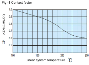
When the temperature of linear guides exceed 100°C, hardness of blocks and rails will be reduced, causing reduction of life. Please compensate the life rating with temperature factor.
* Please use linear guides within the resistant temperature range on product pages.
- ●Contact factor (fC)
-
Table - 1. Contact factor
Number of blocks installed on one rail and contact factor fC
| 1 | 1.00 |
| 2 | 0.81 |
| 3 | 0.72 |
| 4 | 0.66 |
| 5 | 0.61 |
In general, it is common to use 2 or more blocks on 1 rail. In such case, load applicable on each block would not be uniform due to machining variations. As the result, allowable load rating on each block would vary depending on the number of blocks used per rail. Please compensate the life rating with contact factor shown on Table - 1.
- ●Load factor (fW)
-
Table - 2. Load factor
| Application condition | fw |
No external shocks or vibrations and
speed is low 15m/min or less | 1.0 - 1.5 |
No significant shocks or vibration and
med. speed 60m/min or less | 1.5 - 20 |
External shocks and vibrations exist
and the speed is high 60m/min or over | 2.0 - 3.5 |
When calculating loads applicable on linear guides, other than the weight of the object, inertial force due to motion speeds, moment loads, and variations of each over time must also be obtained accurately. However, accurate calculation would be difficult due to repeated starts and stops and various shocks and vibrations. Therefore, the Load Factors shown in Table - 2 are used to simplify the life calculations.
- ●Applicable load calculation method
- When moment loads apply a block, use the following formula to convert the moment load to applicable load.
-

- P: Applicable load (N)
- F: Downward load (N)
- Co: Static load rating (N)
- MA: Allowable static moment - Pitching direction (N・m)
- MC: Allowable static moment - Rolling direction (N・m)
- Lp: Load point distance (m) in pitching direction
- Lr: Load point distance (m) in rolling direction
Back to page top
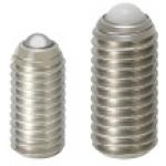
Ball Plunger
| Product name | Ball Plungers/Roller |
| Model number | BPRM6 |
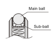
| Characteristic | The combination structure of the main ball and the sub ball facilitates smooth rotation of the ball. |
* Orange colored cells in the table below indicate the part numbers that were actually used in this app. example.
Selection criteria
Popular item that is used as a means of table indexing and position retention.
Back to page top
Risk info.
Retaining force, durability
Back to page top
Available sizes
■Ball Plungers -Roller-
| Ball material | Body | Ball | Sub-ball | Spring | Usable temperature |
| Material | Material | Hardness | Material | Hardness | Material |
| Metal | EN 1.4567 Equiv. | EN 1.4125 Equiv. | 55HRC - | EN 1.4125 Equiv. | 55HRC - | EN 1.4568 Equiv. | -30 ~ 100°C |
| Resin | Polyacetal | - | -30 ~ 80°C |
■Sizes and Dimensions
| Thread DIA. (Coarse) | Ball | Body length |
| DIA. | Stroke |
| M6 | Ø3 | 0.8 | 13 |
| M8 | Ø4 | 1.3 | 15 |
| M10 | Ø5 | 1.6 | 16 |
| M12 | Ø7.1 | 2.3 | 20 |
| M16 | Ø9.5 | 3.1 | 25 |
Back to page top
Mechanism Info.
■Ball plunger (Roller type) structure explanation
The structure with sub-balls below the main ball allows for smooth main ball rotation.
Back to page top
Performance info.
■Spring load of ball plunger (Roller type) (N)
| Thread DIA. (Coarse) | Load (N) |
| min. | max. |
| M6 | 8.1 | 29.6 |
| M8 | 12.6 | 39.8 |
| M10 | 13.5 | 44.4 |
| M12 | 16.1 | 46.9 |
| M16 | 26.1 | 88.2 |
* Min. load is the initial load, max. is when the ball is depressed fully.
Back to page top
Back to page top
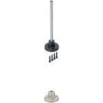
Devise Stand
| Product name | Device Stands - Round Flanged |
| Model number | SCSTN15-200 |
| Characteristic | Stand Set of Low Cost and Standard Shape. |
* Orange colored cells in the table below indicate the part numbers that were actually used in this app. example.
Selection criteria
Since vertical position can be adjusted easily where accuracy is not needed.
Back to page top
Available sizes
■Device Stands - Round Flanged, Pipe
| Post | Bracket | Bracket |
| No dowel hole | With dowel hole |
| Material | Surface treatment | Material | Surface treatment | Post |
| Bar | Pipe | Bar | Pipe |
| EN 1.1191 Equiv. | - | EN-JL 1040 Equiv. | Black oxide
or
phosphate coating | ○ | ○ | ○ | ○ |
| EN 1.1191 Equiv. | Electroless nickel plating | ○ | ○ | ○ | ○ |
| EN 1.4301 Equiv. | - | ○ | ○ | ○ | ○ |
| EN 1.1191 Equiv. | Electroless nickel plating | Electroless
nickel plating | ○ | ○ | - | - |
| EN 1.1191 Equiv. | ○ | ○ | - | - |
| EN 1.4301 Equiv. | - | ○ | ○ | - | - |
(Induction hardening: 58HRC -, Depth 1.0 - 1.5)
■Sizes and Dimensions
| Post DIA. | Overall height | Flange O.D. | Flange height | Flange thickness | (Pipe I.D.) | (Dowel hole DIA.) |
| Ø10 | 50 - 250 | Ø56 | 35 | 12 | Ø6 | Ø6 |
| Ø12 | 50 - 300 | Ø68 |
| Ø15 | 75 - 350 | Ø75 | 40 | Ø10 |
| Ø20 | 75 - 400 | Ø86 | 45 | 12 | Ø11.7 |
| Ø25 | 75 - 450 | Ø100 | 50 | Ø15.2 | Ø8 |
| Ø30 | 100 - 450 | Ø106 | 60 | Ø16 |
| Ø35 | 125 - 500 | Ø118 | 70 | 15 | Ø20.1 | Ø10 |
| Ø40 | 150 - 500 | Ø125 | 80 | Ø22.7 |
| Ø50 | 200 - 600 | Ø140 | 100 | Ø30.8 |
Back to page top
Accuracy Info
■Accuracy info. of devise stand (Round flange, through hole type)
| Post | Bracket | (Dowel hole) |
| O.D. | O.D. tolerance | Shaft bore DIA. | Bore DIA. tolerance | Hole DIA. | Hole DIA. tolerance |
| Ø10 | -0.005 / -0.014 | Ø10 | +0.015 / 0 | Ø6 | +0.012 / 0 |
| Ø12 | -0.006 / -0.017 | Ø12 | +0.018 / 0 |
| Ø15 | Ø15 |
| Ø20 | -0.007 / -0.020 | Ø20 | +0.021 / 0 |
| Ø25 | Ø25 | Ø8 | +0.015 / 0 |
| Ø30 | Ø30 |
| Ø35 | -0.009 / -0.025 | Ø35 | +0.025 / 0 | Ø10 |
| Ø40 | Ø40 |
| Ø50 | Ø50 |
Back to page top
IDEA NOTE Devising of ball plunger engaging position
The mating part of the ball plunger has the notches located slightly lower than the center of the parts height. Regardless of heat treating, when the notches are worn, this part can be turned upside down (use locating dowel pins, etc. to ensure the repeatability) to regain the initial condition.
IDEA NOTE Dual role pins
Locating pins are used to locate the linear guide rail, to prevent the block from falling off.


